

Document Goal
Goal: Provide designers and engineers with practical background information and design guidance for turned parts, with emphasis on manufacturability, process limitations, and cost-conscious geometry choices.
This text is intended as an introductory engineering note rather than as a replacement for detailed production planning by the manufacturer. Final feasibility always depends on the material, machine type, tooling, workholding method, quantity, and inspection requirements.
Turning Background Information
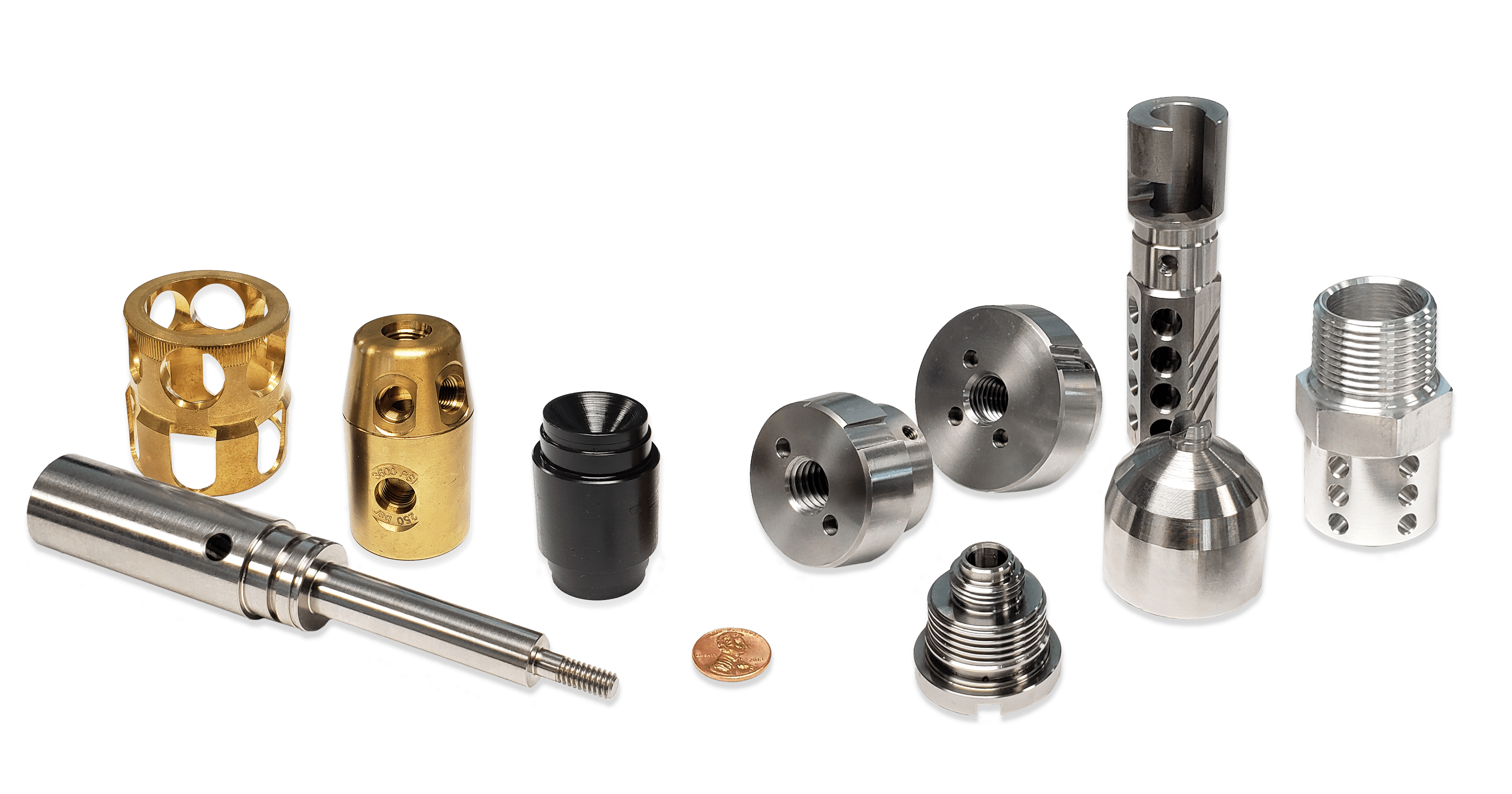
Turning is a chip-removal machining process in which a cutting tool removes material from a rotating workpiece. In the usual arrangement, the part rotates about its axis while the tool is fed in the axial or radial direction to create outer diameters, internal bores, shoulders, grooves, tapers, and similar rotational features.
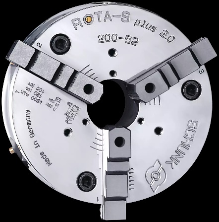
Although turning is mainly associated with round stock, non-round parts can still be machined if they can be clamped securely, for example in an independent 4-jaw chuck. Cylindrical stock is more commonly held in a self-centering 3-jaw chuck, while more specialized workholding solutions are used for demanding geometries.
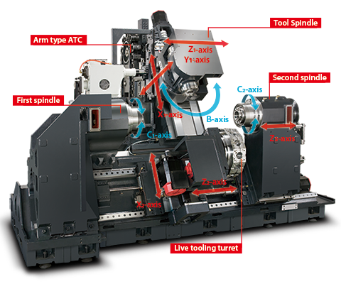
Each machine axis generally represents a defined motion or controlled rotation:
- X-axis: radial movement that mainly changes the machined diameter.
- Z-axis: motion parallel to the spindle axis.
- Y-axis: orthogonal offset motion on more advanced turning centers.
- A-axis: rotation around the X-axis, where present.
- B-axis: rotation around the Y-axis, where present.
- C-axis: controlled spindle rotation around the Z-axis.
Common machine configurations include:
- 2-axis: basic X and Z motion for standard cylindrical parts.
- 3-axis: X and Z plus controlled spindle positioning for secondary operations such as drilling, tapping, or indexed milling.
- 4-axis: typically adds a Y-axis or an equivalent extra capability for off-center work.
- 5-axis: used here as a broad description for more advanced turn-mill systems with additional tilting or multi-directional machining capability.
1.1 Turning Machines
1.1.1 Conventional Lathe
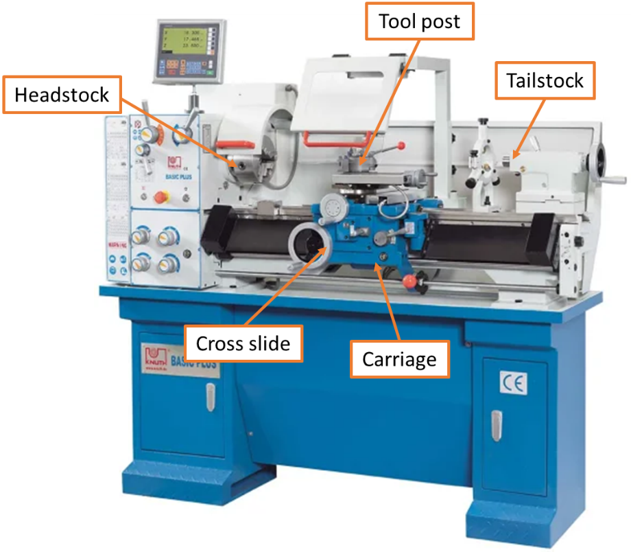
On a conventional lathe, the workpiece is clamped in a chuck or collet and rotated while the cutting tool is guided manually. The part may project from the spindle as a cantilever or be supported at the free end by a tailstock center.
1.1.2 CNC Lathe
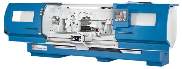
A CNC lathe is a computer numerical control turning machine, not a milling machine, although some machines also include live tooling or milling capability. Compared with a conventional lathe, the motions are driven by a programmed sequence and the machine can usually change tools automatically through a turret.
CNC turning is especially attractive for repeated production because setup and programming effort are incurred once and then reused across the batch. It also reduces manual variability compared with fully conventional machining.
1.1.3 Swiss-Style Lathe
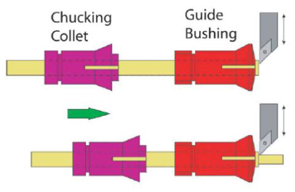
Swiss-type lathes use a different cutting arrangement from conventional lathes. The bar stock feeds axially through a guide bushing, and the cutting tools engage very close to that support point, which greatly improves rigidity for long and slender components.
- The workpiece advances axially through the guide system.
- The tools move in and out radially to remove material.
- The cutting zone remains close to the most rigidly supported part of the workpiece.
1.2 Cutting Tools
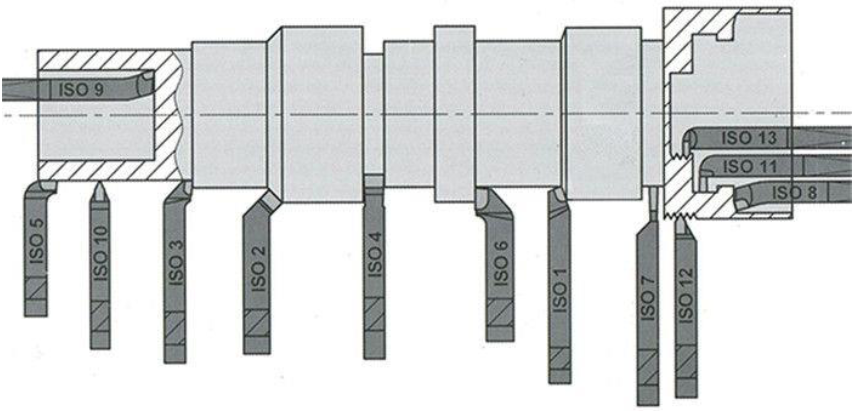
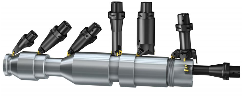
The number of tool types used in a design has a direct effect on cost. A part that can be made with a smaller set of standard inserts, drills, and form tools is usually cheaper to produce than one that requires many special tools or repeated changes.
1.3 Rotary Broaching
Rotary broaching is used to create polygonal internal forms such as hexagons on suitable turning machines. The broach is held at a slight angle to the spindle axis so that, while tool and workpiece rotate together, the cutting edges engage progressively instead of all at once.
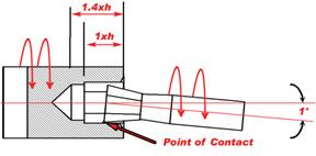

See section 2.11 for design-oriented remarks.
1.4 Knurling
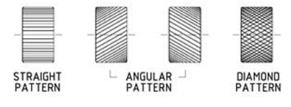
Knurling is generally a forming process in which a patterned wheel presses into the workpiece surface to displace material and create a roughened grip pattern. See section 2.12 for design considerations.
1.5 Threads
Threads on a lathe may be produced by single-point cutting or, for internal threads, by tapping when appropriate. External threads are usually cut on the lathe, while internal threads can be tapped or single-point threaded depending on size, depth, material, and tolerance requirements.
General Rules and Guidelines
Turned parts should be dimensioned clearly enough that all critical diameters, lengths, fits, thread details, and datum relationships are unambiguous. The design should also leave enough usable stock and clamping space for reliable workholding.
2.1 Tolerances / Accuracy
Fine tolerances are achievable in turning and boring, but they should be applied only where function requires them. In typical commercial turning work, tolerances around ±0.1 mm to ±0.2 mm are common, while significantly tighter tolerances demand better machine control, more accurate metrology, and stronger control of thermal effects.
Values such as ±0.005 mm on selected precision features, or even lower on specialized equipment, are possible under controlled conditions. These figures should not be interpreted as standard capability for every feature of every part.
| Category | Tolerance [mm] |
|---|---|
| General commercial turning work | ±0.1 to ±0.2 |
| Carefully controlled precision features | about ±0.005 |
| Specialized ultra-precision setups | can approach ±0.001 in specific cases |
Table 1 – Practical interpretation of tolerance levels
When several critical features must relate closely to one another, it is good practice to machine them in a single clamping wherever possible. This reduces alignment error from rechucking and multiple setups.
2.1.1 Shaft Diameter Accuracy
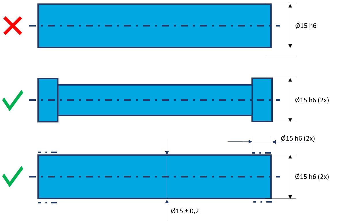
When designing shafts that require ISO fits, consider using standard round bars with pre-defined fits:
- Aluminum: standard fit h11.
- Stainless Steel: standard fits h9 and f8.
Check your supplier for specifications and availability.
Keep high-accuracy shaft sections only where they are functionally needed, and avoid unnecessarily long precision diameters when a shorter controlled region is sufficient.
2.2 Surface Roughness
Surface roughness is influenced mainly by insert nose radius, feed, tool geometry, machine rigidity, spindle speed, and material behavior. Feed and tool nose radius usually have the strongest direct effect, while cutting speed often influences finish more indirectly through temperature, built-up edge, and cutting stability.
| Range | Ra Value | Notes |
|---|---|---|
| Broad turning capability | about 0.2 – 6.3 µm | Possible range depending on setup and process. |
| Typical economical range | about 0.8 – 3.2 µm | Often practical for general turned parts. |
| Specialized ultra-fine turning | can be around 0.05 µm | Only on highly controlled equipment and applications. |
If a very fine finish is not required, more productive feeds can often be used. Any minimum depth of cut should be treated as tool- and material-dependent rather than as a universal fixed value.
2.3 Guidelines for Keeping Costs Low
Minimize setup changes
- Try to make the geometry accessible in as few setups as possible.
Use standard tools
- Choose hole sizes, thread sizes, and groove widths that match standard tooling where possible.
- Reduce the number of tool types required for the part.
Optimize hole features
- Prefer through holes over blind holes where function allows.
- Hole depth below roughly 5× the drill diameter is usually easier with standard tooling.
- Depths greater than about 10× diameter often require special drilling methods or tooling.
- Avoid specifying flat-bottom blind holes where possible; allow for drill-point geometry.
Think about the production route
- For larger series, a design that can be machined efficiently from bar stock and parted off can be advantageous.
2.4 Minimum Internal Corner Radius
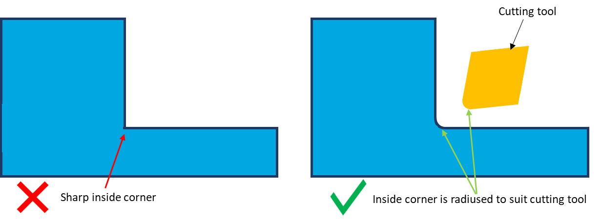
The minimum internal radius specified on the part affects which inserts can be used. Larger radii generally allow more robust tooling and lower cost, while very small radii may require finer tooling, reduced feeds, or additional operations.
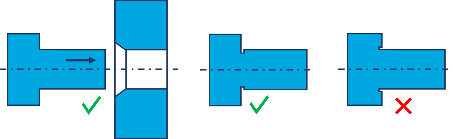
2.4.1 Considerations for Mating Parts
When a mating component seats against a turned shoulder, leave enough clearance for the internal tool nose radius. A chamfer on the mating part, a relief groove, or a standardized undercut can all solve the interference issue, although local stress effects should still be considered.
2.5 Contouring
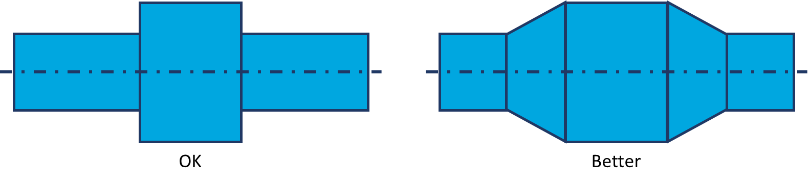
Smooth transitions between different diameters are often preferable to abrupt shape changes. They can simplify the tool path, improve surface continuity, and reduce the number of inserts needed.
2.6 Radial Holes
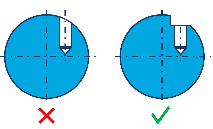
When drilling into a curved cylindrical surface, the drill point tends to wander. Machining a flat at the entry location improves positional stability and generally produces a more reliable hole location.
2.7 Long – Slender Turned Parts
Unsupported length should be limited in relation to diameter. The 10:1 rule of thumb is a useful first check, but the true practical limit depends on stiffness, cutting forces, tolerance requirements, material, and whether support such as a tailstock, steady rest, follow rest, or guide bushing is available.
- If tailstock support is acceptable, the drawing can simply state that centers (in accordance with DIN 332) are permitted, rather than modeling the center geometry explicitly.
- If centers are not allowed, a steady rest or an alternative process route may still make the part feasible.
2.8 Boring
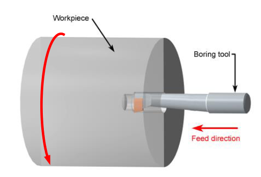
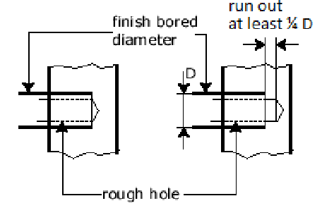
Boring enlarges or finishes an existing hole by removing material from the internal surface with a single-point tool. It is commonly used after drilling when the required diameter control, geometry, concentricity, or finish cannot be achieved by drilling alone.
2.8.1 Boring Design Considerations
Achievable precision
- Surface roughness around Ra 0.8 µm is often realistic.
- Tolerances around ±0.025 mm are frequently achievable.
- Finer values such as ±0.013 mm are possible at higher cost.
Cost and efficiency
- Boring is generally slower and more expensive than drilling, so drilling should be preferred when it already satisfies the requirement.
Geometric limitations
- Avoid deep holes with aspect ratios greater than 3L:1D (length to diameter) if possible as accuracy and cutting time will be compromised.
Blind-hole considerations
- Provide bottom relief or clearance of at least ¼D for tool runout and chip evacuation, sized appropriately for the tool and process.
2.9 Reaming
Reaming is used to size a pre-existing hole accurately within a defined tolerance band. For blind holes, the reamer needs end clearance, so the finished reamed depth must stop short of the hole bottom or drill point. Leave at least 1 mm of clearance to the bottom of the hole.
2.10 Threads
For cut threads (and their run-out), please refer to DIN 76. Consult supplier if deviations are required.
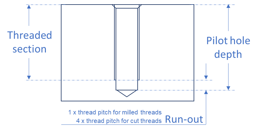
For tapped threads the standard feature in your CAD software suffices. Do note the hole depth. By default, a depth tolerance of ± 1 mm should be maintained. If really needed, ± 0,5 mm is possible, but more expensive.
The pilot hole depth is dependent on the required thread length. The minimum run-out length should be 4 times the pitch of the thread (this allows for the thread to be tapped, as the end of the tap is tapered to give a gradual cutting action). For cut thread, the run-out can be as small as 1 times the thread pitch
If the hole tip comes within 2 mm of the other side of the part, make the hole a through hole. Only deviate from this if a blind hole serves a particular purpose.
For modeling internal threads, use the hole feature in your CAD software.
For modeling external threads, use the threads feature in your CAD software.
2.11 Rotary Broaching
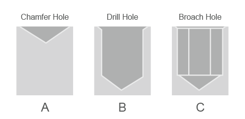
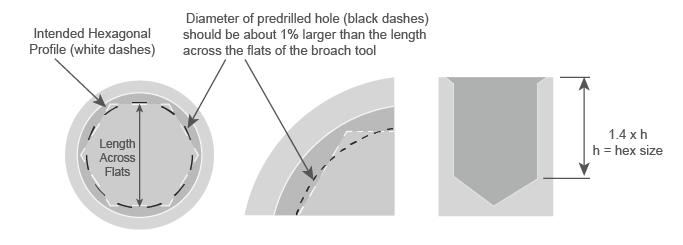
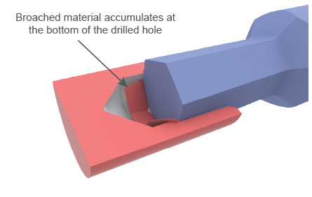
Internal polygonal forms such as hexagons can be produced by rotary broaching on suitable turning equipment. A relief or clearance feature is usually needed to accommodate burrs and broach geometry; without it, a more expensive process such as EDM may be considered.
Typical process sequence:
- Provide an entry chamfer suited to the broach and application.
- Prepare a pilot hole sized appropriately for the desired profile.
- Broach the final internal form.
2.12 Knurling
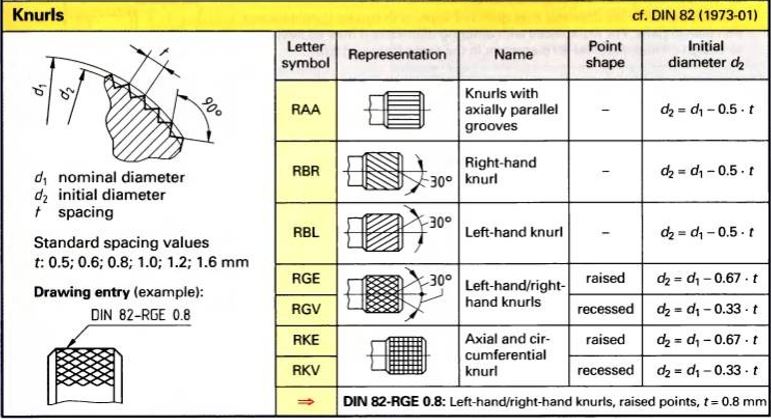
For standardized knurl forms, DIN 82 is a reasonable starting point. Any requested deviation in pitch, pattern, or angle should be checked with the intended supplier beforehand.
2.13 Turning Hardened Products
Hard turning with suitable tooling can be applied to workpieces up to roughly 62 HRC, depending on the material and the severity of interrupted cuts. In the right application, hard turning can replace some cylindrical grinding operations, although finish, geometry, and residual stress requirements still need to be assessed carefully.
Table of References
| Reference | Purpose |
|---|---|
| DIN 76 | Thread reliefs and undercuts. |
| DIN 82 | Knurling definitions and dimensions. |
| DIN 332 | Center holes for turning work. |
| DIN 509 | Relief grooves and undercuts. |