

Document Goal
Goal: Informing engineers of the limitations and guidelines for the design of sheet metal parts. This document provides designers with basic background information and guidelines on the subject of sheet metal parts. There are two main parts to this document:
Sheet Metal Processing Background Information
Sheet metal manufacturing is a process that involves shaping flat sheets of metal into various products and structures. This process typically works with metal sheets ranging from 0.15 mm to 10 mm in thickness, though thicker sheets may be used in some applications.
Sheet metal fabrication offers several advantages:
- Cost-effectiveness, especially for low to medium volume production;
- Versatility in design and application;
- Rapid production and scalability;
- Material conservation with minimal waste.
Sheet metal can be processed in several different ways:
- Conventional processing
- Laser cutting
- Water jet cutting
- Plasma cutting
- Bending
1.1 Conventional Processing
Conventional processing of sheet metal refers to traditional mechanical methods used to shape and cut metal sheets without relying on advanced technologies like lasers or water jets. These methods have been used for decades in metalworking and fabrication industries, offering reliable and cost-effective solutions for many applications. Mainly used for straight-forward cuts.
Advantages:
- Cost-effectiveness: Generally lower equipment and operating costs compared to advanced cutting methods like laser cutting.
- Versatility: Suitable for a wide range of materials and thicknesses.
- No heat-affected zone: Unlike thermal cutting methods, conventional cutting doesn't alter the material properties through heat.
- Simplicity: Many conventional cutting methods are straightforward to learn and operate.
Limitations:
- Precision: May not achieve the same level of precision as advanced methods like laser cutting.
- Speed: Can be slower than some modern cutting techniques, especially for complex shapes.
- Material waste: Some methods, like shearing, may produce more waste than precision cutting techniques.
- Tooling costs: For processes like blanking, initial tooling costs can be high for specific shapes.
1.1.1 Shearing
Shearing is one of the most widely used conventional cutting techniques for sheet metal. This process involves two sharp blades, typically made of high-grade tool steel, positioned one above the other. The upper blade descends to cut the metal sheet placed below, creating a clean, straight cut.
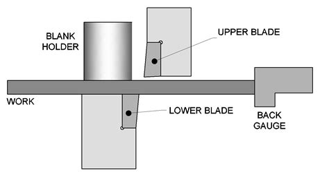
Key features of shearing:
- Ideal for making straight-line cuts on flat sheet metal.
- Commonly used in mass production due to its speed and efficiency.
- Suitable for cutting metal sheets of varying thicknesses, though typically used for thinner materials.
- Often employed in preliminary shaping of metal before further processing.
1.1.2 Sawing
Sawing is a versatile method for cutting sheet metal, especially for thicker materials or when making long, straight cuts. Types of saws include: band saws, circular saws, and reciprocating saws.
1.1.3 Nibbling
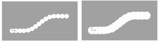
Nibbling is a special case of punching where a tool that is open on one side is used to line up many holes on a sheet edge. This method allows for:
- Creating a parting line;
- Free shaping;
- Tool-independent cutting process;
- Complex shape creation.
This does create burrs between the "nibbles" as shown in Figure 2.
1.1.4 Punching / Blanking / Stamping
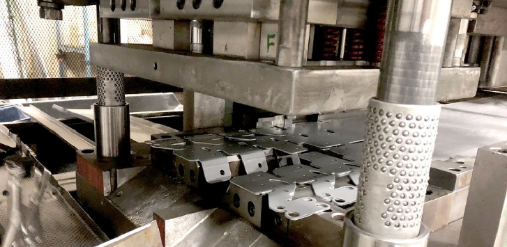
Punching and blanking are similar processes that use a punch and die to create holes or cut-out specific shapes from sheet metal through massive shearing forces.
Key features of blanking:
- Precisely cuts out a product from sheet metal (the cut-out is the desired product). Excess material becomes scrap.
- Suitable for high-volume production of specific shapes.
Key features of punching:
- Creates holes or specific shapes in sheet metal.
- Can be used for decorative purposes or to prepare metal for other processes.
- Often used in conjunction with other cutting methods.
Stamping is a more encompassing term including punching, blanking, and embossing. These processes are mostly used with high production volumes.
1.1.5 Deep Drawing
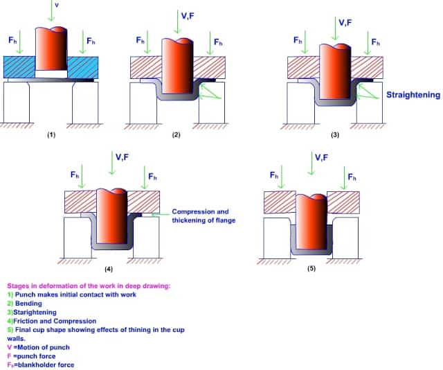
Deep drawing is a sophisticated sheet metal forming process that transforms flat metal sheets into hollow, three-dimensional shapes with depths greater than their diameters. This technique is widely used in high production volume manufacturing to produce seamless, complex parts with minimal material waste.
The deep drawing process involves several key steps:
- A flat sheet metal blank is cut to size (usually through blanking).
- The blank is positioned over a shaped die cavity.
- A blank holder applies pressure to the sheet's edges to control material flow.
- A punch pushes the metal into the die cavity, causing it to flow and conform to the desired shape.
- The formed part is removed from the die.
1.2 Laser Cutting
A precise cutting method that uses a laser to cut or engrave metal by heating and burning it. The laser beam is focused and directed by a lens or mirror onto the material's surface, where it heats and melts or vaporizes the metal along the designated cutting path.
Two primary types of lasers are commonly used for sheet metal cutting:
- CO₂ Lasers: suitable for cutting, boring, and engraving a wide range of materials.
- Fiber Lasers: more efficient for cutting reflective metal materials like copper and aluminum.

The main advantages of laser cutting are:
- Precision: Laser cutting offers extremely high precision (±0.1 mm, up to ±0.3 mm depending on material and thickness). See ISO 9013.
- Speed: It can cut through metal much faster than traditional methods.
- Minimal Material Waste: The narrow kerf (width of cut) results in less material waste.
Cutting thickness:
- Carbon Steel — up to 25 mm
- Stainless Steel — up to 20 mm
- Aluminium — up to 8 mm (up to 10 mm with worse tolerancing)
- Copper & brass — difficult due to reflections (contact your supplier)
- Titanium — up to 8 mm (up to 10 mm with worse tolerancing)
1.3 Water Jet Cutting
Water jet cutting operates by forcing water through a small diamond or ruby orifice at extremely high pressures, typically between 30,000 to 90,000 PSI. For cutting metals, an abrasive (usually garnet) is added to the water stream. Some waterjets can perform 5-axis cutting for complex shapes.
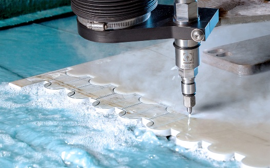
The main advantages of water jet cutting are:
- Versatility: Water jet cutting can handle a wide range of materials and thicknesses.
- No Heat-Affected Zone: Unlike thermal cutting methods, water jet cutting does not create a heat-affected zone, preserving the material's properties.
- Precision: It offers high precision (±0.2 mm in the worst case, up to ±0.05 mm), allowing for intricate designs and clean cuts.
- Minimal Material Waste: The narrow kerf (width of cut of approx. 1 mm) results in less material waste.
- Environmentally Friendly: The process uses water and natural abrasives.
A cutting depth of up to 250 mm is possible in virtually any material.
1.4 Plasma Cutting
This process utilizes a high-temperature, electrically conductive gas to melt and cut through conductive materials, primarily metals. Plasma cutting operates by creating an electrical channel of superheated, electrically ionized gas, known as plasma. The process begins with compressed air or another gas being forced through a small nozzle at high speed. An electrical arc is then formed between an electrode near the nozzle and the metal being cut. This arc rapidly heats the gas, turning it into plasma, which is hot enough to melt the metal and fast enough to blow away the molten material.
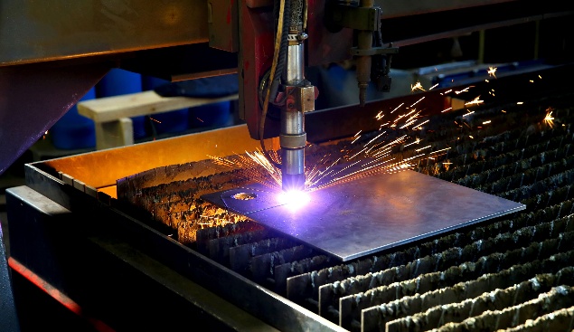
Plasma cutting falls between water jet and laser cutting in terms of thickness capability. The main advantages are:
- Precision: Plasma cutting offers high precision, allowing for intricate designs and clean cuts.
- Speed: It can cut through metal much faster than traditional methods like oxy-fuel cutting.
- Versatility: Plasma cutters can handle a variety of conductive metals, including steel, aluminum, and stainless steel.
- Minimal Heat-Affected Zone: The process produces a smaller heat-affected zone compared to other thermal cutting methods, resulting in less metal distortion.
| Mild Steel | Stainless Steel | Aluminium | |
|---|---|---|---|
| Clean Cut Thickness | 30 mm | 16 mm | 16 mm |
| Severance Thickness | 35 mm | 20 mm | 20 mm |
Table 1 – Maximum plasma cutting thickness
Thicker materials may be possible, but that depends on too many factors (mostly on the power of the cutting machine). Discuss with manufacturer.
1.5 Bending
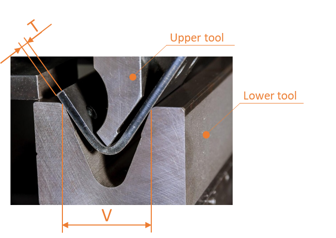
Sheet metal bending involves applying force to a metal sheet to change its geometry beyond its yield strength, causing permanent deformation without breaking or failing. The process typically uses a press brake, which lowers a punch onto a sheet metal positioned on a die to create the desired shape.
Common bending methods:
- V-bending: the most common method, using a V-shaped die and punch to bend metals at desired angles. It can achieve acute, obtuse, or 90° bend angles depending on the tooling. Using bottoming, additional force after bending is applied to reduce springback.
- Air Bending: a flexible method where the sheet metal doesn't touch the bottom of the die, allowing for various bend angles with a single set of tools.
- Roll Bending: uses sets of rollers to form metal sheets into rolls, tubes, cones, or curved shapes.
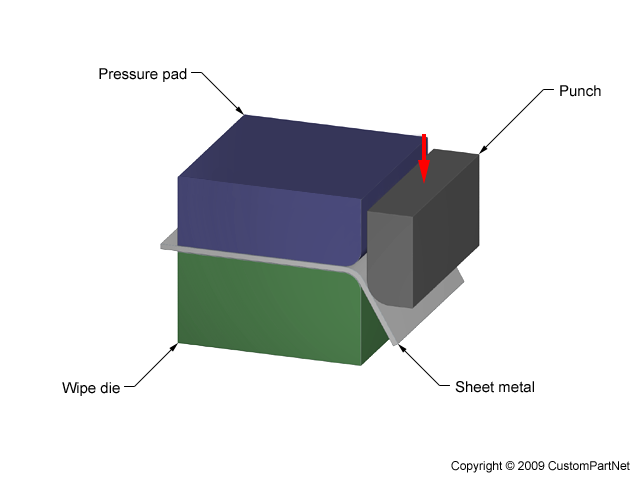
- Wipe Bending: the sheet is held against a wipe die by a pressure pad, and the punch forces the extending edge to bend over the die end.
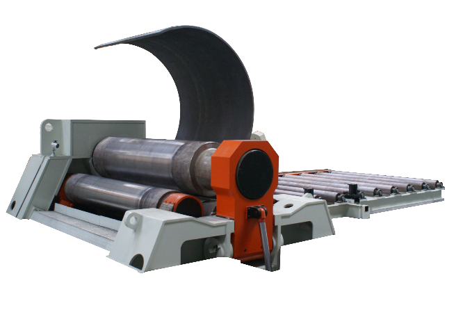
Advantages of Sheet Metal Bending:
- Versatility in creating complex shapes.
- Cost-effective for both small and large production runs.
- Ability to work with a wide range of materials and thicknesses.
- High precision and repeatability, especially with CNC-controlled machines.
| V-code | V-groove width [mm] | LTW (outside width) [mm] | Used for sheet thickness [mm] |
|---|---|---|---|
| V6 | 6 | 20 | 0.8 |
| V8 | 8 | 20 | 1 + 1.25 |
| V10 | 10 | 20 | 1.5 |
| V12 | 12 | 25 | — |
| V16 | 16 | 30 | 2 + 2.5 |
| V20 | 20 | 30 | 3 |
| V24 | 24 | 40 | — |
| V30 | 30 | 40 | 4 |
| V40 | 40 | 50 | 5 + 6 |
| V50 | 50 | 75 | 8 |
| V60 | 60 | 75 | — |
Table 2 – Relationship between lower tool groove width (LTW) and sheet thickness
As a rule of thumb, the V-code used is the smallest V-code that complies to the formula:
V code > sheet thickness × 6
This is supplier dependent — when in doubt, contact your supplier.
General Rules and Guidelines
When designing a sheet metal part, keep in mind the desired production method, as that will define the ideal feature size and tolerance. In general, the following must be considered:
- Design all features on one side of the workpiece to minimize the number of setups required. This may reduce lead time and helps with feature accuracy.
- Make sure that all features can be accessed.
- Always make sure the unfolded part is not larger than the source material.
2.1 Laser Cutting
- Make sure that the laser kerf (cut width) can be accommodated. This is dependent on the plate thickness.
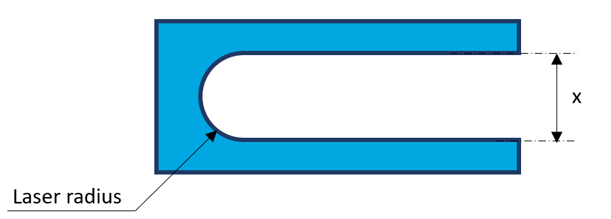
| Laser radius [mm] | Minimum size x [mm] |
|---|---|
| 0.1 × T | 2 × laser radius |
Table 3 – Laser kerf accommodation
- Add radii everywhere if possible, the minimum sizing corresponding to Table 3. This prevents the laser from making an extra turn, which would cause an increase of the effective cut width at corners, an increase in local heat input, and slows down the cutting process.
- Keep in mind a cutting tolerance of ± 0.1 mm.
- Hole diameter > 0.5 × material thickness (with a minimum of 0.5 mm).
- Space between cut features > 2 × material thickness.
- Make sure that all features are larger than indicated in Table 4.
| Sheet thickness [mm] | Min. feature – Steel [mm] | Min. feature – Stainless [mm] | Min. feature – Aluminium [mm] |
|---|---|---|---|
| 1 | 0.5 × T | 0.5 × T | 0.5 × T |
| 1.5 | 0.5 × T | 0.5 × T | 0.5 × T |
| 2 | 0.5 × T | 0.5 × T | 1.5 |
| 3 | 0.5 × T | 0.5 × T | 2.5 |
| 4 | 0.5 × T | 0.5 × T | 2.5 |
| 5 | 0.5 × T | 0.5 × T | 3.5 |
| 6 | 2.4 | 0.5 × T | 4 |
| 8 | 5 | 3.1 | 5 |
Table 4 – Minimum feature size
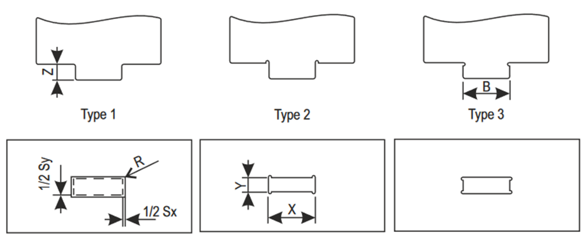
When designing tab-slot connections for laser cutting the following guidelines shall be taken into consideration. Note that this applies only for laser cutting. Other tolerance buildups must also be taken into account.
There is no specific minimum or maximum for the tab height (Z). When tab-slots for connecting two parts are placed perpendicular to each other: add 2 mm to Sx (as each width already defines the part position in one translation).
- Type 2 is for thin materials.
- Type 3 is for thick materials.
| T [mm] | Min. tab length B [mm] | Type 1 – Play Sx [mm] | Type 1 – Play Sy [mm] | Type 2&3 – Play Sx [mm] | Type 2&3 – Play Sy [mm] |
|---|---|---|---|---|---|
| 1 | 2 | 0.4 | 0 | 0 | 0 |
| 1.25 | 2 | 0.4 | 0 | 0 | 0 |
| 1.5 | 3 | 0.4 | 0 | 0 | 0 |
| 2 | 3 | 0.4 | 0 | 0.05 | 0.05 |
| 2.5 | 4 | 0.4 | 0 | 0.05 | 0.05 |
| 3 | 4 | 0.4 | 0.1 | 0.05 | 0.05 |
| 4 | 5 | 0.2 | 0.4 | 0.1 | 0.1 |
| 5 | 5 | 0.2 | 0.4 | 0.1 | 0.1 |
Table 5 – Tab-slot dimensions (X = B + Sx, Y = T + Sy)
2.2 Water Jet Cutting
- Make sure that the water jet kerf (cut width of 1.2 mm or larger) can be accommodated. This also defines the smallest allowable hole.
- Keep in mind a cutting tolerance of ± 0.2 mm.
- Space between cut features > 3.5 mm.
- Add at least 0.5 mm radii everywhere if possible (reduces cutting time).
2.3 Bending
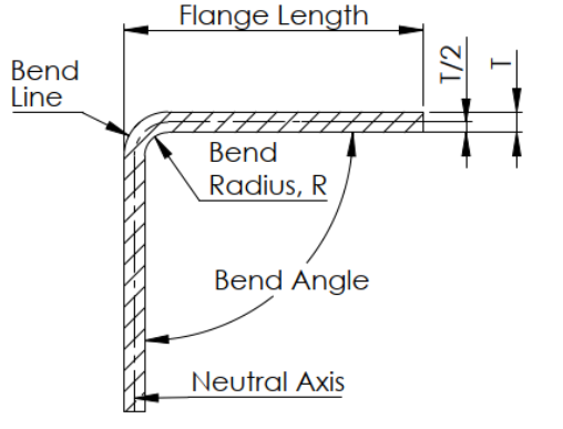
Sheet metal bend brakes are used to bend material into the part's desired geometry. Bends that are in the same plane need to be designed in the same direction to avoid part re-orientation, saving both money and time. Keeping the bend radius consistent through all bends will also make parts more cost-effective.
2.3.1 Preferred Bend Radii
When the required bend radius is less than recommended, this can cause material flow problems in soft material and fracturing in hard material. Localized necking or fracture may also occur in such cases. The tables below provide guidelines for several materials. Always check with the supplier based on the specific material.
For bend radius tolerancing the following values can be used:
- Radius ≤ 1 mm → Tolerance = ± 0.5 mm
- 1 mm ≤ Radius ≤ 4 mm → Tolerance = ± 1 mm
- Radius > 4 mm → Tolerance = 0.5 × sheet thickness
| Material | Treatment | Recommended radius (R) |
|---|---|---|
| Carbon steel | Hot or cold rolled | 1 × thickness |
| 1.4310 Stainless steel AISI 301 | Cold rolled | 3 × thickness |
| 1.4301 Stainless steel AISI 304 | Cold rolled | 1 × thickness |
| 1.4301+2B Stainless steel AISI 304 | Cold rolled – Quality 2B | 1 × thickness |
| 1.4306 Stainless steel AISI 304L | Annealed | 1 × thickness |
| 1.4401 Stainless steel AISI 316 | Annealed | 1 × thickness |
| 1.4404 Stainless steel AISI 316L | Annealed | 1 × thickness |
| 3.3315 EN-AW 5005 | H14 / H24 | 0.5 ≤ T < 3.0 mm → 1 × thickness 3.0 ≤ T < 6.0 mm → 2 × thickness |
| 3.3535 EN-AW 5754 | O / H32 / H11 / H111 | 0.5 ≤ T < 1.5 mm → 1.0 × thickness 1.5 ≤ T < 6.0 mm → 1.5 × thickness 6.0 ≤ T < 12 mm → 2.5 × thickness |
| 3.2315 EN-AW 6082 | T6(6) | 4 × thickness (only parallel to the rolling direction) |
Table 6 – Recommended material bend radii
2.3.2 K-factor
The K-factor is the ratio between the neutral axis and the thickness of the material. The K-factor is used to calculate flat patterns, as it is related to how much the material is stretched during bending. By default, the K-factor in most software is set to 0.5.
Because every supplier has different machines with different correction factors (K), it is impossible to know and take this into account beforehand. Therefore, part models and drawings are usually supplied in bent state only, it is then up to the supplier to comply with the part requirements and to correctly prepare the part for their machine(s).
2.3.3 Allowable Bend Angle
The sheet metal must always be bent a bit further than the indicated angle due to material rebound. The tools for air bending have a maximum angle of 30°, which allows for:
- Plate thickness ≤ 4 mm: bends of up to 33° when taking rebound into account. The minimum angle to be bent is 175°.
- Plate thickness > 4 mm: bends of up to 67°. The minimum angle to be bent is 175°.
2.3.4 Flange Dimensions / Tolerancing
Due to the tooling used, there are limits to the flanges that can be made.
2.3.4.1 Minimum / Maximum Flange Length
The minimum flange length is caused by what size of lower tool is used for the bend. This corresponds to 0.5 × the lower tool groove width + radius mould + 1 mm.
| Sheet thickness [mm] | Min. flange length for steel and aluminium [mm] | Min. flange length for stainless steel [mm] | Min. flange length for higher strength steel (S355) [mm] |
|---|---|---|---|
| 0.8 | 6 | 6 | - |
| 1 | 6 | 6 | - |
| 1.25 | 6.6 | 6.5 | - |
| 1.5 | 7.5 | 8 | 9 |
| 2 | 9.5 | 9.5 | 11.5 |
| 2.5 | 12 | 12.5 | - |
| 3 | 12.5 | 15.5 | 17 |
| 4 | 18 | 18 | 22 |
| 5 | 23 | 30 | 29 |
| 6 | 30 | 42 | 30 |
| 8 | 43 | 42.5 | 53.5 |
| 10 | 44 | 57 | - |
Table 7 – Minimum flange length at 90° bends
| Thickness [mm] | Max. Steel [mm] | Max. Stainless [mm] | Max. Aluminium [mm] |
|---|---|---|---|
| ≤ 3 | 4300 | 4300 | 4300 |
| 3 ≤ 4 | 3900 | 4300 | 4300 |
| 4 ≤ 5 | 3000 | 4300 | 4300 |
| 5 ≤ 6 | 2500 | 4000 | 4300 |
Table 9 – Maximum flange length
| Sheet thickness [mm] | Min. flange length for steel and aluminium [mm] | Min. flange length for stainless steel [mm] | Min. flange length for higher strength steel (S355) [mm] |
|---|---|---|---|
| 0.8 | 10 | 10 | - |
| 1 | 10 | 10.5 | - |
| 1.25 | 10.5 | 10.5 | - |
| 1.5 | 10.5 | 10.5 | 12 |
| 2 | 12.5 | 12.5 | 12.5 |
| 2.5 | 15.5 | 15.5 | - |
| 3 | 21.5 | 21.5 | 21.5 |
| 4 | 22 | 22.2 | 22 |
| 5 | 23 | 30 | 29 |
| 6 | 30 | 42 | 30 |
| 8 | 43 | - | 42.5 |
Table 8 – Minimum flange length at sharp bends
2.3.4.2 Minimum Flange Width
The smallest flange width is 20 mm as this is dependent on the lower tool groove width (see Table 2). Any narrower should be discussed with the supplier. Hand bending could be an option depending on the material, material thickness, and whether or not a relief can be added.
2.3.4.3 Maximum Flange Width
Take into consideration that, for bending, the product weighs no more than 60 kg. Discuss with the supplier when deviating from this and/or reference the table below.
| Sheet thickness [mm] | Max. width – Steel [mm] | Max. width – Stainless [mm] | Max. width – Aluminium [mm] |
|---|---|---|---|
| 1 to 4 | 3000 | 3000 | 3000 |
| 5 | 3000 | 2600 | 3000 |
| 6 | 3000 | 2200 | 3000 |
| 8 | 2200 | 1500 | 3000 |
Table 10 – Maximum flange width
2.3.4.4 Flange Tolerancing
In general, ISO 2768-cL shall be used for bent sheet metal parts. If more detail is required, continue below (see Table 11 and Table 12 for allowable tolerances).
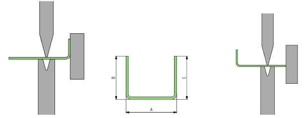
There are two ways to bend a U-shape after the first bend is produced. The most critical dimension (i.e. the dimension with the narrowest tolerances) defines how the part must be fed into the bending machine:
- Bending as shown on the left side of Figure 14 will deliver a part where the A dimension has the most precise tolerance.
- Bending as shown on the right side of Figure 14 will deliver a part where the A dimension is less precise, but where the C dimension will be more precise.
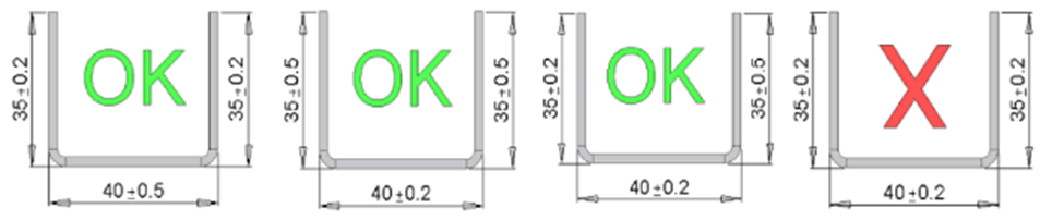
When the tolerance class "fine" is used for a flange, one of the tolerances next to the "fine flange" must have a "coarse" category (especially for U- and Z-bend shapes). This principle is shown in Figure 15 and the tolerance values can be seen in Table 11 and 12.
| Sheet thickness [mm] | Flange length [mm] | Fine [mm] | Medium [mm] | Coarse [mm] |
|---|---|---|---|---|
| 0.8 ≤ T ≤ 2.0 | 0 < L ≤ 300 | ± 0.20 | ± 0.30 | ± 0.50 |
| 300 < L ≤ 1000 | ± 0.30 | ± 0.50 | ± 1.00 | |
| 1000 < L ≤ 4300 | ± 0.50 | ± 1.00 | ± 1.50 | |
| 2.0 < T ≤ 3.0 | 0 < L ≤ 300 | ± 0.30 | ± 0.45 | ± 0.75 |
| 300 < L ≤ 1000 | ± 0.45 | ± 0.75 | ± 1.50 | |
| 1000 < L ≤ 4300 | ± 0.75 | ± 1.50 | ± 2.25 | |
| 3.0 < T ≤ 5.0 | 0 < L ≤ 300 | ± 0.40 | ± 0.60 | ± 1.00 |
| 300 < L ≤ 1000 | ± 0.60 | ± 1.00 | ± 2.00 | |
| 1000 < L ≤ 4300 | ± 1.00 | ± 2.00 | ± 3.00 | |
| 5.0 < T | 0 < L ≤ 300 | ± 0.50 | ± 0.75 | ± 1.25 |
| 300 < L ≤ 1000 | ± 0.75 | ± 1.25 | ± 2.50 | |
| 1000 < L ≤ 4300 | ± 1.25 | ± 2.50 | ± 3.75 |
Table 11 – Flange length tolerance classes
| Sheet thickness [mm] | Flange length [mm] | Fine [°] | Medium [°] | Coarse [°] |
|---|---|---|---|---|
| 0.8 ≤ T ≤ 2.0 | 0 < L ≤ 300 | ± 0.20 | ± 0.30 | ± 0.50 |
| 300 < L ≤ 1000 | ± 0.30 | ± 0.50 | ± 1.00 | |
| 1000 < L ≤ 4300 | ± 0.50 | ± 1.00 | ± 1.50 | |
| 2.0 < T ≤ 3.0 | 0 < L ≤ 300 | ± 0.30 | ± 0.45 | ± 0.75 |
| 300 < L ≤ 1000 | ± 0.45 | ± 0.75 | ± 1.50 | |
| 1000 < L ≤ 4300 | ± 0.75 | ± 1.50 | ± 2.25 | |
| 3.0 < T ≤ 5.0 | 0 < L ≤ 300 | ± 0.40 | ± 0.60 | ± 1.00 |
| 300 < L ≤ 1000 | ± 0.60 | ± 1.00 | ± 2.00 | |
| 1000 < L ≤ 4300 | ± 1.00 | ± 2.00 | ± 3.00 | |
| 5.0 < T | 0 < L ≤ 300 | ± 0.50 | ± 0.75 | ± 1.25 |
| 300 < L ≤ 1000 | ± 0.75 | ± 1.25 | ± 2.50 | |
| 1000 < L ≤ 4300 | ± 1.25 | ± 2.50 | ± 3.75 |
Table 12 – Flange angular tolerance classes
2.3.4.5 U-shaped Bends
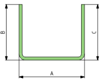
The manufacturability of U-shapes depends on the following criteria:
- Profile dimensions (inside and outside dimensions);
- Proportions of A/B and A/C;
- Sheet thickness.
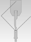

General rules:
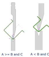
- U-shapes which comply to A ≥ B can be bent (see Figure 17). When A < B and C, contact your supplier or redesign the part.
- Dimensional limits (see Figure 18 and Figure 19):
- A=B=C ≥ 140 mm: possible collision with upper tool clamping (discuss with supplier);
- A=B=C < 25 mm: possible collision with upper tool (discuss with supplier).
2.3.4.6 Z-shaped Bends
The manufacturability of Z-shapes depends on the size of dimension x with respect to the sheet metal thickness and material.
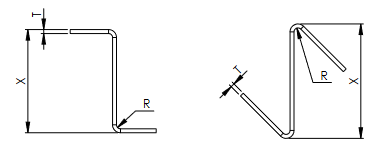
| Sheet thickness [mm] | Min. X – Steel [mm] | Min. X – Stainless Steel [mm] | Min. X – Aluminium [mm] |
|---|---|---|---|
| 1 | 8.5 | 8.7 | 8.5 |
| 1.5 | 10.7 | 11 | 10.7 |
| 2 | 13.8 | 14.2 | 13.8 |
| 3 | 20.1 | 24.8 | 20.1 |
| 4 | 26.2 | 27.4 | 26.2 |
| 5 | 34.7 | 44.4 | 34.7 |
| 6 | 42.9 | 63.2 | 42.9 |
| 8 | 62.2 | — | 62.2 |
Table 13 – Z-shaped bend minimum dimensions
2.3.5 Bend Reliefs
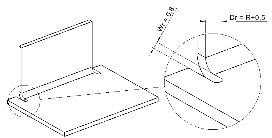
When bending, the bend will bulge, which can cause issues with surrounding features. Therefore, a relief should be added near a bend to make space for the material bulging. The dimensions should be at least:
- Width relief (WR) = 0.8 mm
- Depth relief (DR) = inside bend radius + 0.5 mm
2.3.6 Hemming
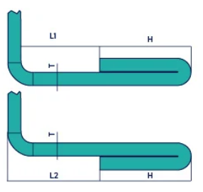
For hemming the following considerations apply:
- Material: Steel or Stainless steel
- Sheet metal thickness ≤ 2 mm
- Flange length (H) ≤ 14 mm
- Distance to other flange (L1) ≥ 6 mm
- Distance to other flange (L2) ≥ 13 mm
- Minimum room in between hem flanges = 0.01 mm
2.3.7 Other Features Near a Bend
If there are features near a bend, they can deform or bulge in unwanted ways during the bending process. To maintain the correct shape, follow the guidelines in this section.
2.3.7.1 Holes
To maintain the intended hole shape, the hole must be placed a certain minimum distance away from the bend. Use the following formulas to determine the proper distance:
- Round holes → C = R + 2·T
- Slotted/square holes:
- for b ≤ 25 mm → C = R + 3.3·T
- for 25 < b ≤ 50 mm → C = R + 3.5·T
- for b > 50 mm → C = R + 4.0·T
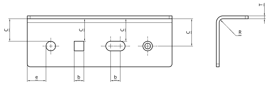
When a larger V-groove is used in the making of the bend, the required distance (C) increases:
- V groove = 6·T → As stated above.
- V groove = 8·T → Apply an additional 1.2·C, as compared to above.
- V groove > 8·T → Apply an additional 1.5·C, as compared to above.
Alternatively, a hole relief can be added (see section 2.3.7.2).
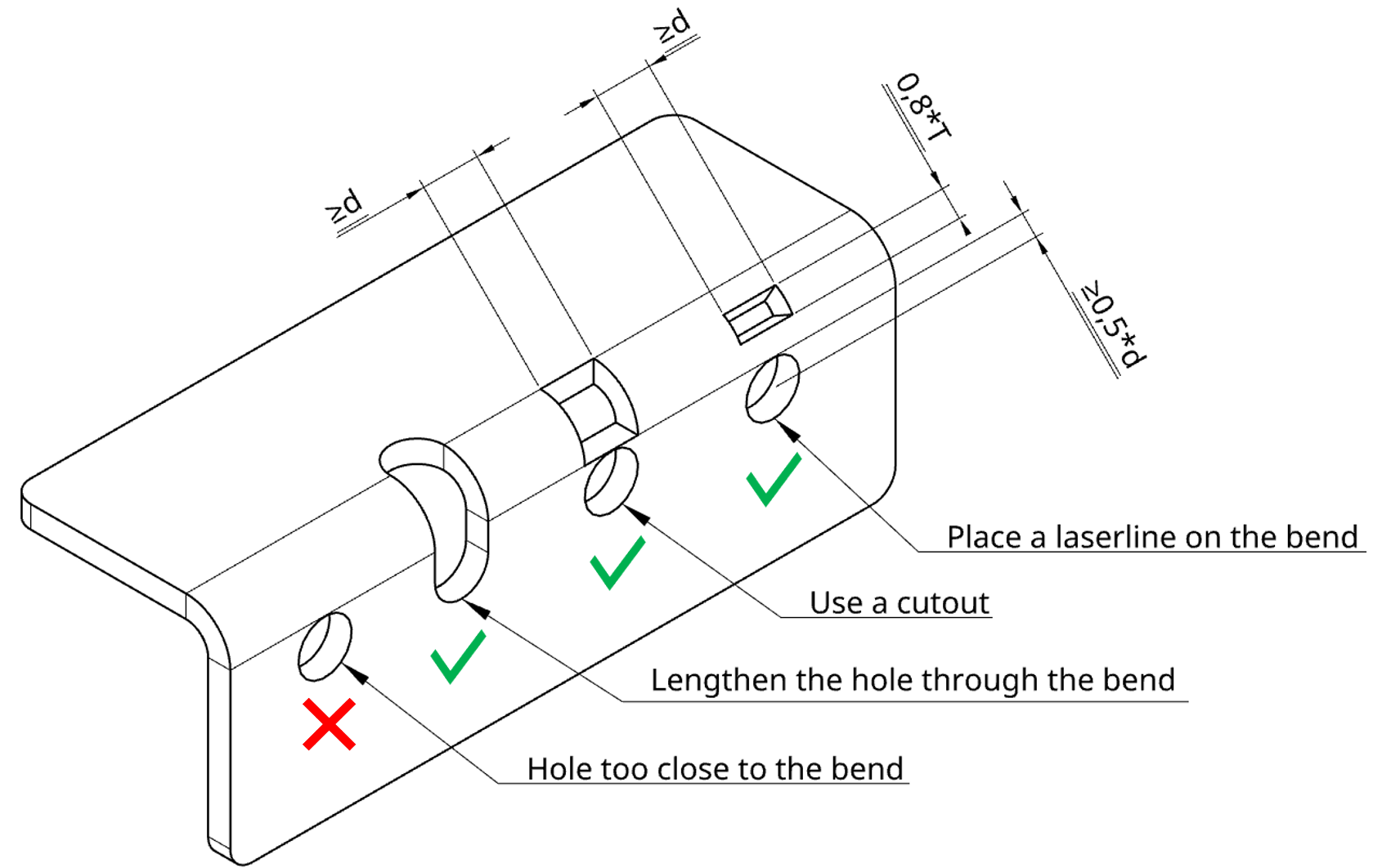
2.3.7.2 Hole Relief
Use a hole relief in accordance with Figure 24 if a hole needs to be closer to the bend than the distance specified in section 2.3.7.1. This can be done for any hole shape.
2.3.7.3 Cut-outs
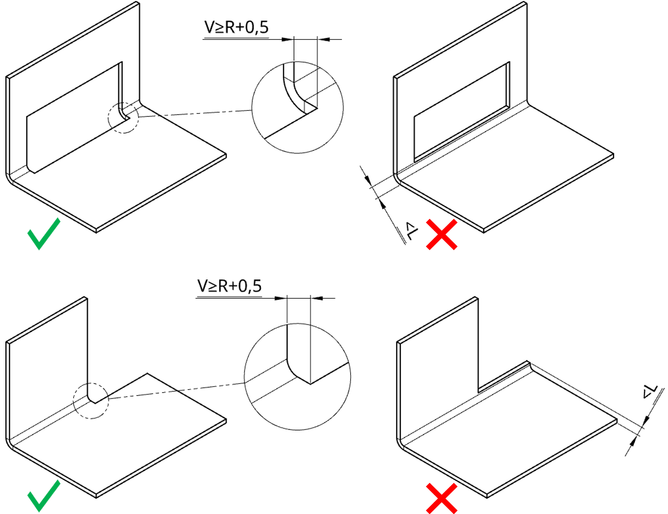
To prevent bulging it is strongly preferred to extend a cut-out past a bend when a cut-out almost intersects a bend. Very small edges (smaller than the minimum flange length as shown in Table 7 and 8) will not follow the bend contour and will bulge.
2.3.7.4 Chamfers
Chamfers at or near a bend will deform during bending. To prevent this deformation, make sure that U > 4·T.
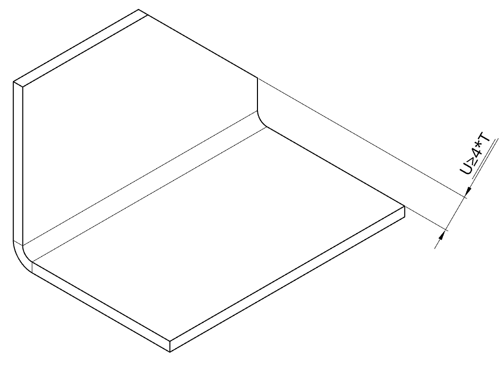
Table of References
| Reference | Purpose |
|---|---|
| ISO 9013 | Laser cutting tolerances |
| ISO 2768-cL | General tolerances for bent sheet metal parts |