

Document Goal
Goal: Give designers and engineers practical background information and design guidance for milled metal parts, with emphasis on manufacturability, tool access, geometric limits, and cost-conscious feature definition.
Milling Background Information
Milling is a machining process in which a rotating cutter removes material from a workpiece. As the cutter teeth cyclically engage and disengage, they shear away chips and create faces, slots, shoulders, pockets, and more complex contours.
1.1 Milling Machines
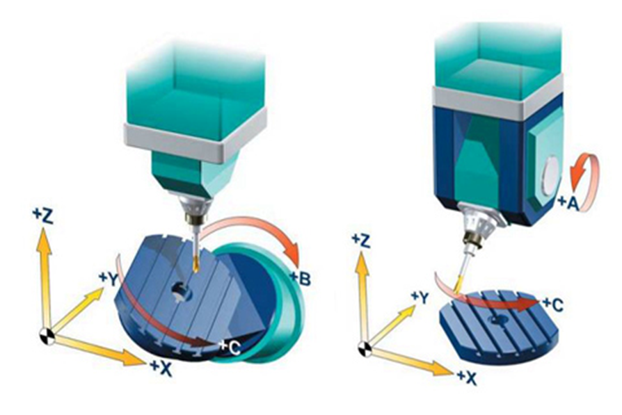
Milling machines are commonly classified by the number of controlled axes available:
- 3-axis milling: The cutter moves along the X, Y, and Z linear axes.
- 4-axis milling: As above, with 3-axis motion plus one rotary axis, either indexed or simultaneous depending on the machine configuration (A, B, or C).
- 5-axis milling: Three linear axes and two rotary axes; the exact kinematics depend on the machine architecture. In practice, this is not typically an A-and-B pairing.
- 6-axis milling: A broad label sometimes applied to more articulated or multi-rotary systems, although it is less standard in everyday shop-floor terminology.
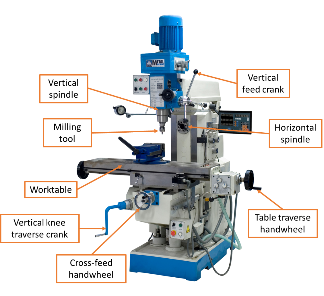
1.1.1 Vertical Milling Machine
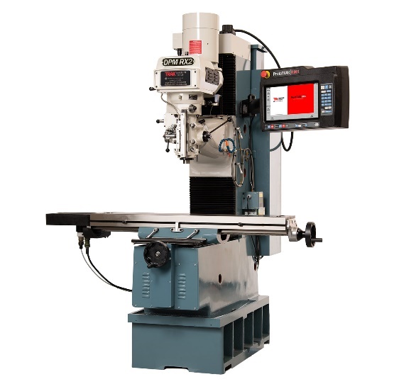
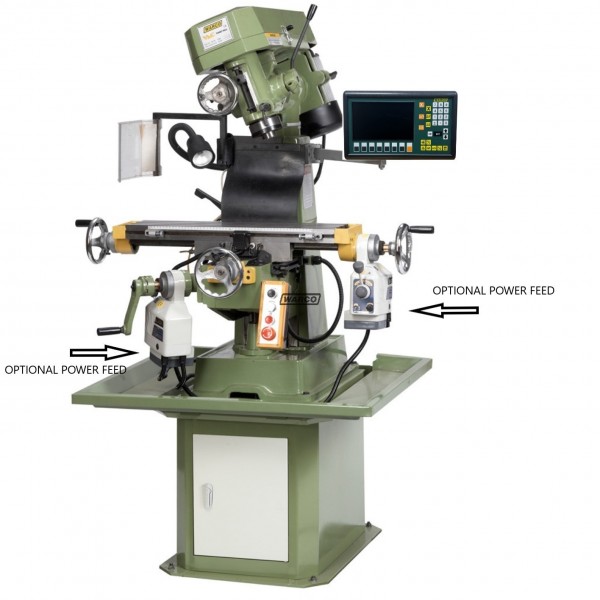
Vertical milling machines have a spindle axis oriented vertically. The cutter is mounted in the spindle and rotates about its axis; the spindle can be lowered, or the table raised, to permit plunge cutting and drilling. Two main subcategories are commonly distinguished:
- Bed mill: The worktable moves only perpendicular to the spindle axis (the Z-axis), while the bed moves only in the horizontal plane (the X and Y axes).
- Turret mill: The spindle remains fixed while the table provides vertical movement. This arrangement is more versatile but generally less rigid than a bed mill. Some models also include a quill, allowing vertical cutting by moving the quill up and down or by moving the knee.
1.1.2 Horizontal Milling Machine
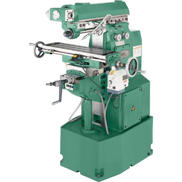
A horizontal milling machine has a spindle parallel to the worktable rather than perpendicular to it. It uses a horizontal arbor carrying various cutting tools and is typically more robust, making it well suited to larger workpieces and heavy roughing operations.
1.1.3 Universal Milling Machine
A universal milling machine can be arranged as either a horizontal or a vertical machine and can accept attachments such as an indexing head, slotting attachment, or rotary table. Its worktable can swivel up to 45° in either direction, enabling helical milling. It is often used to produce tooling such as cutters, reamers, and drills.
1.1.4 CNC Milling Machine
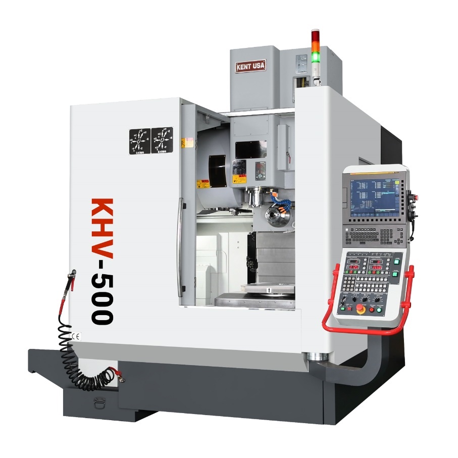
CNC (Computer Numerical Control) milling machines are operated by a programmed computer control system. Although setup time is higher, CNC machines can change tools automatically via a tool changer and are well suited to complex geometries that require simultaneous multi-axis motion. They become cost-effective for larger production runs because setup time is incurred only once per batch, while the risk of human error is greatly reduced.
1.2 Cutting Tools
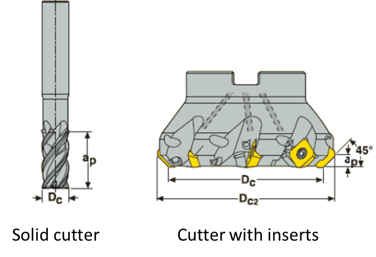
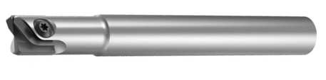
Cutters are broadly divided into two categories: solid cutters and cutters with inserts. Solid cutters are typically selected below a cutting diameter Dc of 12–16 mm (steel, SST, titanium) or 20–25 mm (aluminium, plastics). Above these diameters, cutters with inserts are more practical.
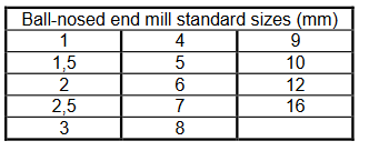
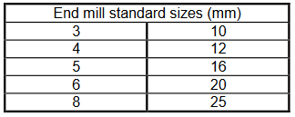
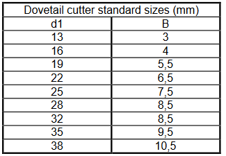
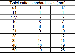
The most common cutter types are end mills, face mills, T-slot cutters, metal slitting cutters, fly cutters, and form cutters. Standard sizes for the most frequently used types are listed below. For a complete overview, consult tool supplier catalogues such as Dormer Pramet or Seco.
1.2.1 End Mill Tools
Unlike drills, which cut only axially, end mills can cut in multiple directions. They can be used for plunging, reaming, slotting, drilling, face milling, profile milling, and other operations. Common types include:
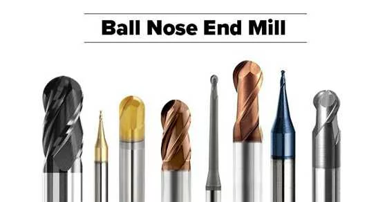
Ball mill cutter: These have hemispherical tips, allowing a corner radius to be maintained where perpendicular faces meet.
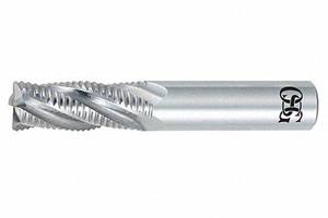
Square end mill: This general-purpose cutter has a 90-degree profile and is well suited to operations such as plunging, profiling, and slotting.
Bull nose cutter: This is similar to a square end mill but has a rounded edge, which provides greater corner strength.
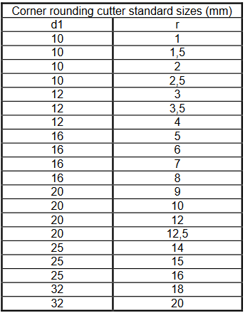
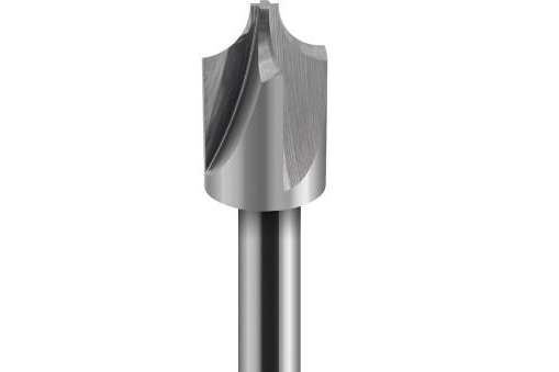
Radius/rounding end mill: Its rounded geometry is well suited to producing a specified radius uniformly, helping to reduce cutter wear and extend tool life.
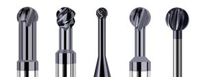
Undercutting mill (lollipop cutter): This tool is well suited to machining undercuts and offers high versatility because of its rounded head shape.
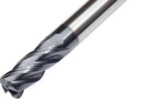
Roughing end mill: Serrated flutes accelerate cutting. Because multiple teeth contact the workpiece at the same time, chatter is reduced and material can be removed quickly.
Chamfer end mill: Its angled corners allow chamfers to be machined in locations that standard tools may not reach easily.
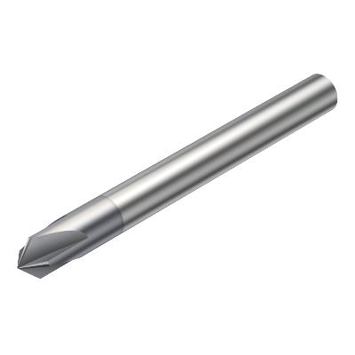
Dovetail end mill: This cutter is intended specifically for machining dovetail slots.

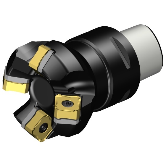
1.2.2 Face Mill Tools
Face mills do not cut axially. Instead, their cutting edges are located around the head, and the teeth are usually replaceable carbide inserts. These tools are available in sizes from about 10 to 500 mm.
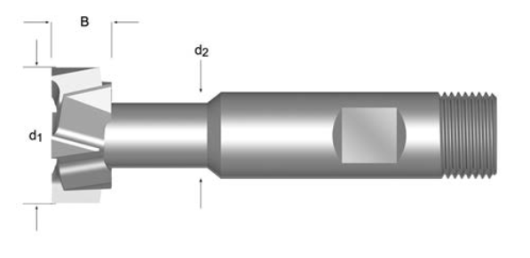
1.2.3 T-Slot Cutters
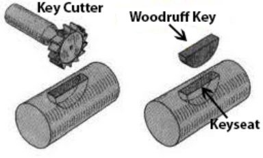
T-slot cutters have teeth perpendicular to the outside diameter and are best known for cutting T-shaped slots. A similar-looking tool is the Woodruff cutter, designed exclusively for Woodruff key slots. This means that Woodruff cutters cannot cut with the sides of their teeth!
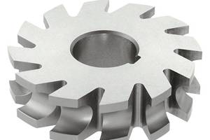
1.2.4 Metal Slitting Cutters
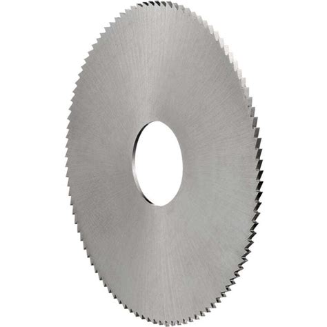
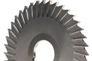
These are essentially saws used on a milling machine. Common types are:
- Plain slitting cutter: This type has only peripheral cutting edges, with side concavity to reduce drag.
- Side teeth slitting cutter: This type has both peripheral and side teeth to maintain a consistent cutting width.
- Concave milling cutter: This cutter is used to produce a true convex radius.
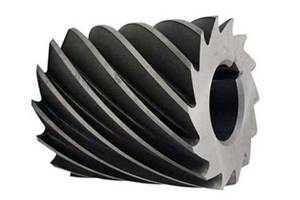
- Cylindrical milling cutter: This type has only peripheral teeth and is suited to high stock-removal rates.
1.2.5 Fly Cutters
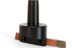
Fly cutters perform the same basic function as face mills but at lower cost. They consist of a central body that holds one or two tool bits, and those bits are often made in-house by a machinist rather than bought ready-made.
1.2.6 Form Milling Cutters
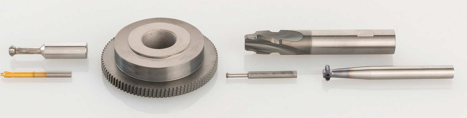
Form milling cutters are used to machine irregular 2D and 3D contours. They are well suited to helical gears and other complex surfaces. Because so many custom shapes exist, the image serves only as an example of what is possible.
General Rules and Guidelines
When designing a part for milling, the following general principles apply regardless of the feature involved:
- Use standard tool sizes wherever possible (see Section 1.2).
- Minimise the number of cutting tools required.
- Design features so that the largest practical cutter diameter can be used. Larger cutters are less prone to breakage and can operate at lower spindle speeds.
- Place all features on one side of the workpiece where possible to minimise setups, shorten lead time, and improve feature accuracy.
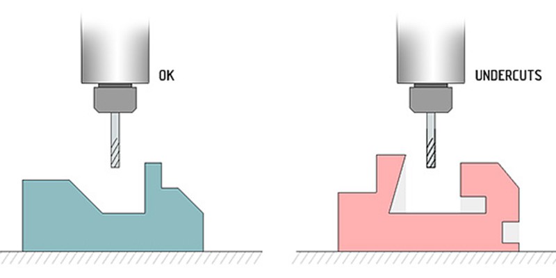
- Ensure that every feature is accessible to the cutter, considering width, depth, and clearance for both tool and holder.
- Avoid thin features with height-to-width ratios greater than 30:1.
- Avoid undercuts where possible; if they are required, use standard tools (see Section 1.2) and account for the stress concentrations they introduce.
2.1 Milling Outer Surfaces
Where a high degree of surface accuracy or flatness is required, pads and bosses are preferred over fully machined surfaces. These reduce the controlled area and clearly define reference surfaces.
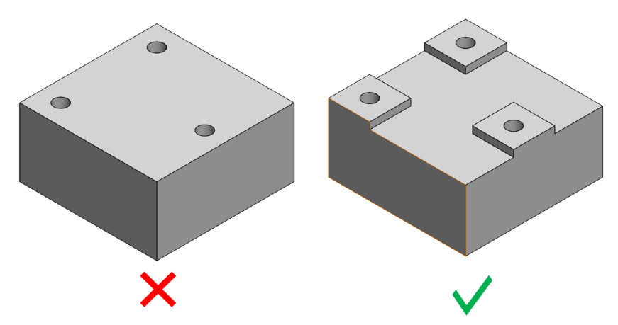
Avoid square corners because they are fragile and prone to denting. Rounded edges are preferred. The spacing between bosses should be at least the size of a standard cutter plus 2 mm to allow for post-machining.
Table 1 – Recommended distance between bosses
| Recommended distance [mm] | Mill used Dc [mm] |
|---|---|
| 3 | 1 |
| 4 | 2 |
| 5 | 3 |
| 6 | 4 |
| 7 | 5 |
| 8 | 6 |
| 10 | 8 |
| 12 | 10 |
| 14 | 12 |
| 18 | 16 |
| 22 | 20 |
| 27 | 25 |
For good milling accessibility, design horizontal surfaces so one cutter can machine them all, and design shoulders so that a true 90° shoulder can be produced.
2.1.1 Outer Surface Fillets/Chamfers
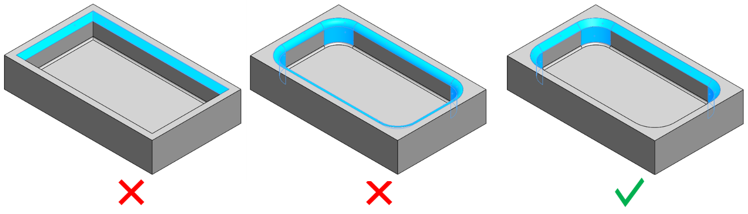
Edges on tops of pockets, bosses, outside corners, and slots should be chamfered, not filleted. An outside fillet requires a special cutter and a precise setup, both are expensive.
2.1.2 Outer Surface Roughness
A surface roughness Ra between 1.6 and 3.2 μm is readily achievable. In certain cases, Ra 0.3 μm can be obtained through careful control of machining parameters.
Surface roughness increases if: feed rate fz decreases, cutting speed vc increases, or the nose radius of the cutter increases.
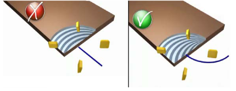
Tip: Allow for a clockwise circular cutter movement on entry and exit. This produces thick chips on entry and small chips on exit, eliminating jitter and reducing Ra. Linear run-in/run-out produces thick chips on exit, increasing Ra.
2.2 Milling Walls
Milling very thin walls is generally only practical on high-speed milling machines. High-speed milling is significantly more expensive than conventional milling and is therefore usually not preferred.
2.2.1 Aluminium Walls
In aluminium, walls as thin as 1.25 mm are possible with a height-to-thickness ratio of up to 30:1, although this has a significant effect on surface roughness. Walls thinner than 0.5 mm generally do not survive the milling process, though capabilities continue to improve, so always discuss this with your supplier.
As a guideline, the maximum height H of a wall created with a single pass must not exceed 10× the remaining thickness t adjacent to the cut. For example: a wall roughed to 3 mm allows adjacent milling passes up to 30 mm deep. Finishing passes to 1.25 mm final thickness are limited to 12.5 mm depth.
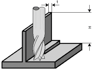
Table 2 – The 10-to-1 rule for aluminium wall height
| Wall thickness [mm] | Max. axial depth of cut [mm] |
|---|---|
| 0.5 | 5 |
| 0.6 | 6 |
| 0.7 | 7 |
| 0.8 | 8 |
| 0.9 | 9 |
| 1.0 | 10 |
| 1.1 | 11 |
| 1.2 | 12 |
2.2.2 Steel, Stainless Steel, and Titanium Walls
The same h-to-t principle applies, but the ratio changes to 8-to-1. Thinner walls are achievable with these materials.
Table 3 – The 8-to-1 rule for Steel, Stainless Steel, and Titanium wall height
| Wall thickness [mm] | Max. axial depth of cut [mm] |
|---|---|
| 0.1 | 0.8 |
| 0.2 | 1.6 |
| 0.3 | 2.4 |
| 0.4 | 3.2 |
| 0.5 | 4.0 |
| 0.6 | 4.8 |
| 0.7 | 5.6 |
| 0.8 | 6.4 |
| 0.9 | 7.2 |
| 1.0 | 8.0 |
2.3 Milling Pockets
Pockets are milled by plunge milling, ramping, helical interpolation, or a combination (see Appendix A). The pocket width must be at least 1.1 Dc. Pay attention to depth limitations and provide relief if greater depth is required.
2.3.1 Pocket Depth
Per-step depth limits for solid cutters are:
- Up to 4:1 length-to-diameter for SST and Titanium.
- Up to 5:1 for Aluminium.
Limit the final pocket depth to 6–7 Dc of the end mill. Deeper milling with longer end mills increases roughness and decreases accuracy due to chatter. If long end mills are unavoidable, implement clearances (steps or a relief angle) of ≥ 0.1 mm after every milling step.
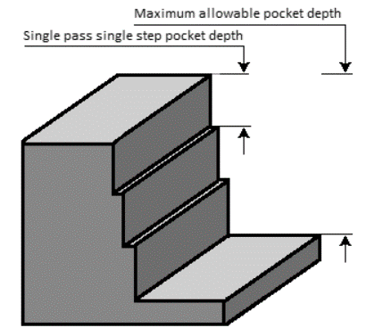
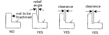
Table 4 – Pocket depth for Titanium and (Stainless) Steel
| Mill Dc [mm] | Single step depth [mm] | Max. allowable depth [mm] |
|---|---|---|
| 5 | 17.5 | 75 |
| 6 | 21 | 90 |
| 8 | 28 | 120 |
| 10 | 35 | 150 |
| 12 | 42 | 180 |
| 16 | 56 | 240 |
| 20 | 70 | 300 |
Table 5 – Pocket depth for Aluminium
| Mill Dc [mm] | Single step depth [mm] | Max. allowable depth [mm] |
|---|---|---|
| 5 | 25 | 75 |
| 6 | 30 | 90 |
| 8 | 40 | 120 |
| 10 | 50 | 150 |
| 12 | 60 | 180 |
| 16 | 80 | 240 |
| 20 | 100 | 300 |
2.3.2 Pocket Bottom Fillets/Chamfers
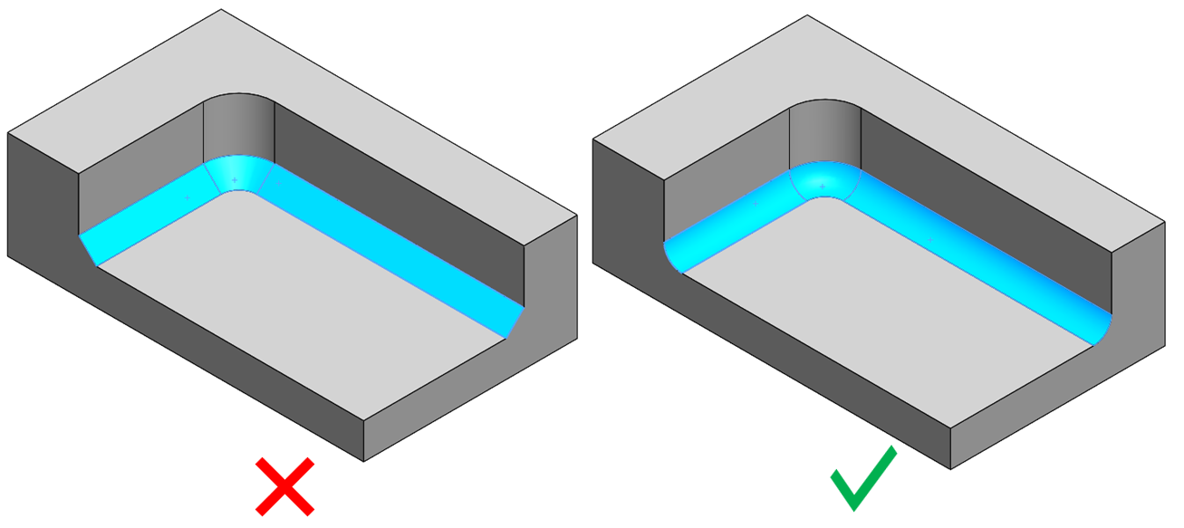
Milled pockets can include a chamfer between the side walls and the base. A chamfer is generally not preferred, but if one is required it should be large enough to match at least the size of a chamfer end mill. Where possible, let the supplier determine inside radii so there is flexibility in tool selection and cost can be reduced.
If the detail is critical, match the fillet to the end radius of a standard bull-nose cutter (refer to supplier catalogues). This helps extend tool life; a larger radius or chamfer requires an additional machining step and therefore increases cost.
2.3.3 Pocket Corners
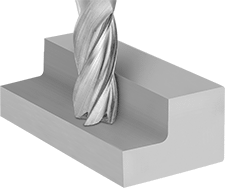
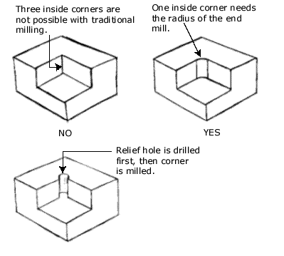
Sharp inside corners cannot be produced by milling, they require more expensive methods like EDM. At least one inside edge of a three-edge corner must have the radius of the end mill (or larger). If a sharp corner is needed for mating clearance, drill a separate relief hole first (drills cannot withstand significant side loading).
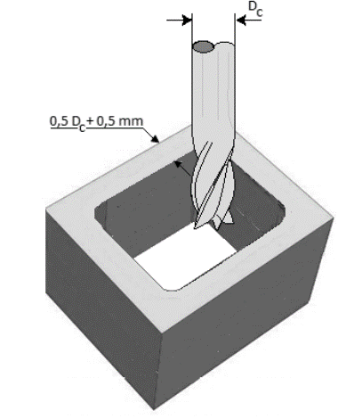
The minimum acceptable corner radius for end mills cutting in Titanium, Stainless Steel, or Aluminium is 0.5 Dc + 0.5 mm. Omitting the 0.5 mm addition causes the cutter to dwell at the radius and increases surface roughness.
Where possible, allow the supplier to determine inside radii. This gives more freedom to use tools that are readily available and easy to maintain.
Table 6 – Minimum corner radius for end mill cutters
| Min. corner radius [mm] | Mill used Dc [mm] |
|---|---|
| 1.0 | 1 |
| 1.5 | 2 |
| 2.0 | 3 |
| 2.5 | 4 |
| 3.0 | 5 |
| 3.5 | 6 |
| 4.5 | 8 |
| 5.5 | 10 |
| 6.5 | 12 |
| 8.5 | 16 |
| 10.5 | 20 |
2.3.4 Through Pockets
Edges of through pockets must be at least 0.5 Dc + 0.5 mm from the side wall.
2.3.5 Slots
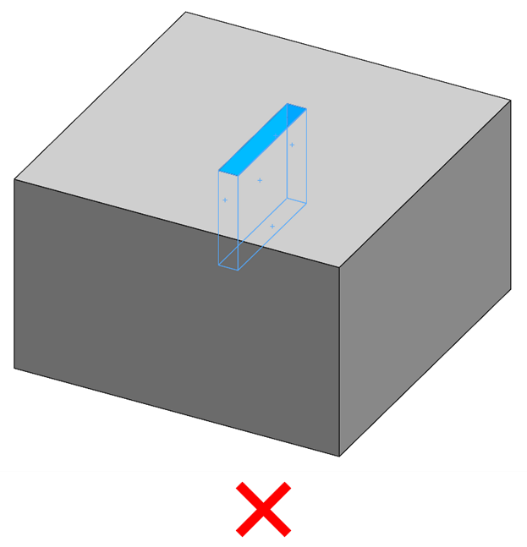
Avoid pockets and slots that are both narrow and deep. Longer tools are more susceptible to breakage, and chip evacuation becomes difficult, especially in blind pockets. Consider saw-cut slits as an alternative (see Sections 1.2.3 and 1.2.4).
2.3.6 Angular Milling Faces
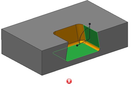
Side and bottom faces of milling features should be at 90° to each other to allow production with a standard end mill. Angular faces require multi-axis machining, which increases cost significantly.
2.4 Threaded Holes
Threaded holes must be pre-drilled and can be milled or cut. Milled thread diameters smaller than M3 are not preferred. While M1.6 is possible, process reliability and bolt handling deteriorate significantly compared to M3.
2.4.1 Hole Accuracy
For pilot holes up to M10, a positional accuracy of Ø0.2 mm is readily achievable. Once threaded, positional accuracy decreases as the effective hole diameter increases.
2.4.2 Pilot Hole Depth
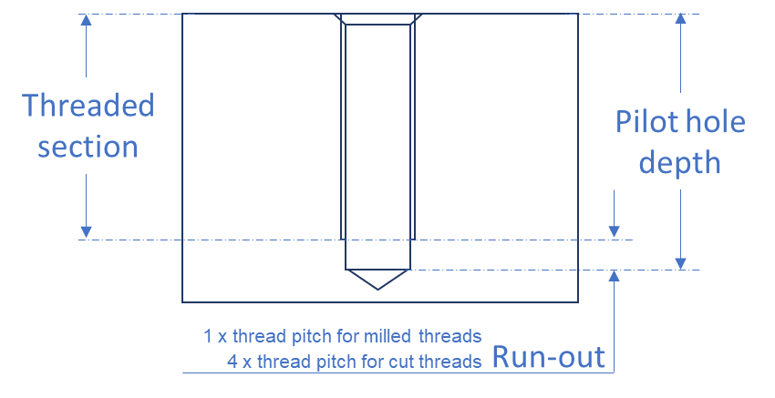
Default depth tolerance: ± 1 mm. If required, ± 0.5 mm is possible but more expensive. The minimum run-out length should be 4× the thread pitch for tapped threads, or 1× the thread pitch for milled (cut) threads. If the hole tip comes within 2 mm of the opposite face, make it a through hole.
2.4.3 Pilot Holes Near Walls
At least 1.5 mm of material must be present between the edge of a threaded hole and the pocket wall. The hole edge must also be at least 0.5 Dc + 0.5 mm from any workpiece edge. Ensure the pocket wall allows clearance for the tool shank to reach the hole.
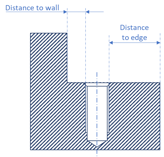
Table 7 – Minimum distance between a wall and a hole edge
| Pilot hole diameter [mm] | Min. distance to wall [mm] |
|---|---|
| 1 | 1.0 |
| 2 | 1.5 |
| 3 | 2.0 |
| 4 | 2.5 |
| 5 | 3.0 |
| 6 | 3.5 |
| 8 | 4.5 |
| 10 | 5.5 |
| 12 | 6.5 |
| 14 | 7.5 |
| 16 | 8.5 |
| 18 | 9.5 |
| 20 | 10.5 |
| 22 | 11.5 |
| 24 | 12.5 |
2.4.4 Asymmetrically Ending Holes
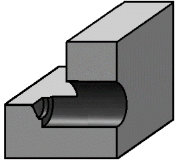
Holes that partially end in material and partially break through are asymmetrically ending holes. These must be milled rather than drilled.
2.4.5 Holes Intersecting Cavities
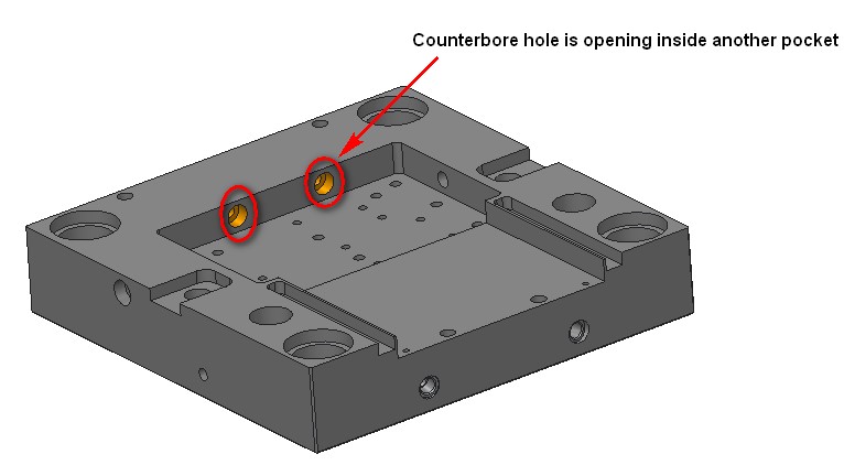
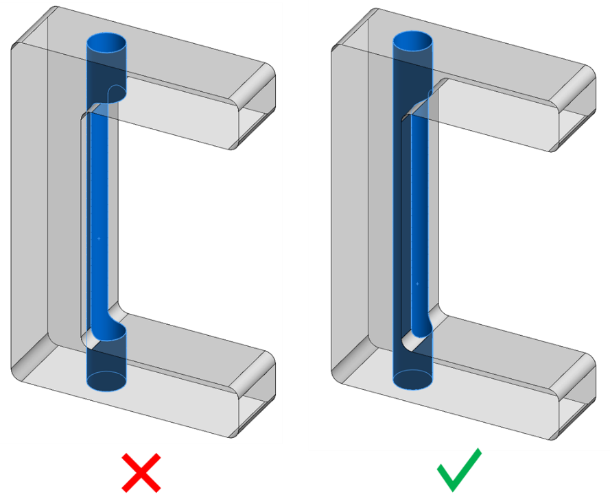
Holes should not intersect a cavity. If unavoidable, the hole centreline must be outside the cavity. During machining, a drill follows the path of least resistance. When at a cavity intersection there is a significant risk of drill wander upon re-entry.
Appendix A – Milling Parameters for Cutters with Inserts
The tables below show limiting parameters for each milling operation. The available cutting-depth range for a given diameter depends largely on the cutter diameters available from the supplier. Always verify exact values against supplier catalogues such as Dormer Pramet or Seco.
Table 8 – Plunging parameters
| Milling cutter used | Cutting diameter [mm] | Max. cutting depth per step [mm] |
|---|---|---|
| Face milling cutter | 24 – 500 | 3.5 – 5 |
| Square shoulder and slot milling cutter | 10 – 250 | 5 – 17 |
| Plunge milling cutter | 12 – 200 | 2.5 – 50 |
Table 9 – Ramping parameters
| Milling cutter used | Cutting diameter [mm] | Max. ramp angle [°] |
|---|---|---|
| Square shoulder and slot milling cutter | 10 – 250 | 1 – 3 |
| High-feed milling cutter | 10 – 200 | 2 – 8 |
| End mill (solid) | 1 – 25 | 2 – 15 |
Table 10 – Helical ramping parameters
| Milling cutter used | Cutting diameter [mm] | Helix diameter [× Dc] | Max. axial depth per pass [mm] |
|---|---|---|---|
| Square shoulder and slot milling cutter | 10 – 250 | 1.5 – 4× | 0.5 – 3 |
| End mill (solid) | 1 – 25 | 1.2 – 3× | 0.1 – 2 |
Table 11 – Milling with long overhangs
| Overhang-to-diameter ratio (L/D) | Recommended reduction in cutting parameters |
|---|---|
| 3:1 | No reduction required |
| 4:1 | Reduce feed by ~20% |
| 5:1 | Reduce feed by ~40% |
| >6:1 | Not recommended; consult supplier |
Table 12 – Milling with unstable conditions
| Condition | Recommended action |
|---|---|
| Excessive vibration / chatter | Reduce cutting speed vc by 20–30% |
| Poor chip evacuation | Increase coolant flow; reduce feed fz |
| Thin-wall deflection | Apply h-to-t rule (see Section 2.2); use finishing passes |
| Tool wear (premature) | Check run-out; verify coating suitability for material |
Table of References
| Reference | Purpose |
|---|---|
| Dormer Pramet | Tool catalogue covering standard cutter sizes and cutting parameters. |
| Seco | Tool catalogue covering standard cutter sizes and cutting parameters. |