

Document Goal
Goal: Informing engineers of the limitations and guidelines for the design of casting parts. This document provides designers basic background information and guidelines on the subject of casting parts. There are two main parts to this document:
- Casting background information.
- General rules and guidelines.
Terminology
Metal casting processes use the following terminology:
- Cavity: the outer mould part / empty part of the mould.
- Chaplet: long vertical holding rod for core that after casting it become the integral part of casting, provide the support to the core.
- Cope: the top half of the pattern, flask, mould, or core.
- Core: an insert in the mould that produces internal features in the casting, such as holes. Also used as the inner mould part / filled part of the mould.
- Core box: the mould or die used to produce the cores.
- Core print: the region added to the pattern, core, or mould used to locate and support the core.
- Draft: the taper on the casting or pattern that allow it to be withdrawn from the mould.
- Drag: the bottom half of the pattern, flask, mould, or core.
- Downgate: a type of gate located at the bottom of the mould. Downgates are designed to introduce the molten metal into the mould cavity from below, which can help in reducing turbulence and ensuring a smoother fill of the mould.
- Downgate pegs: pegs or pins used to create or support the downgates. The pegs help in forming these gates and ensuring they remain in place during the casting process.
- Flask: the rigid wood or metal frame that holds the moulding material.
- Gates: the controlled entrances from the runners into the mould cavities.
- Gating system: the network of connected channels that deliver the molten material to the mould cavities. The gating system typically includes several parts: the pouring basin, sprue, runners, and gates.
- Hot runner: an assembly of heated components used in plastic injection molds that inject molten plastic into the cavities of the mold.
- Kiss-off: is a small, localized contact point or thin section in a mold where two mold halves or inserts lightly touch or nearly touch. This creates a very thin (often 0.05–0.1 mm) section in the final part, which can act as a natural break point or a hinge.
- Mould cavity: the combined open area of the moulding material and core, where the metal is poured to produce the casting.
- Moulding material: the material that is packed around the pattern and then the pattern is removed to leave the cavity where the casting material will be poured.
- Pattern: an approximate duplicate of the final casting used to form the mould cavity.
- Parting line or parting surface: the interface between the cope and drag halves of the mould, flask, or pattern.
- Pouring cup or pouring basin: the part of the gating system that receives the molten material from the pouring vessel.
- Riser: an extra void in the mould that fills with molten material to compensate for shrinkage during solidification.
- Runners: the horizontal portion of the gating system that connects the sprues to the gates.
- Sprue: the pouring cup attaches to the sprue, which is the vertical part of the gating system. The other end of the sprue attaches to the runners.
- Shut-off: is a feature in a mold or die that prevents molten material (metal or plastic) from flowing into unwanted areas, such as gaps, parting lines, or vents. It ensures that the material stays within the intended cavity and does not leak or flash into other parts of the mold.
- Vents: additional channels that provide an escape for gases generated during the pour.
Casting Background Information
Casting is a manufacturing process that involves pouring molten material into a mould to create a specific shape. The process typically follows these key steps:
- Mould Creation: A mould is prepared with a negative impression of the desired part. The mould material can vary depending on the casting method, including sand, plaster, or metal for reusable moulds.
- Melting: The chosen material (metal or plastic) is heated in a furnace until it becomes molten. The melting temperature varies depending on the material; for example, aluminium melts at about 660°C, while iron melts at around 1538°C.
- Pouring: The molten material is carefully poured into the mould through a hollow channel called a “sprue”, often through a pouring basin that leads to channels called sprues and runners.
- Solidification and Cooling: The material cools and solidifies within the mould. This stage is critical as it influences the microstructure and properties of the final product.
- Removal: Once solidified, the casting is removed from the mould. For single-use moulds, this often involves breaking the mould, while permanent moulds have opening arrangements.
- Finishing: The cast part undergoes post-processing, which may include removing excess material, surface finishing, and potentially heat treatment.
The choice of casting method depends on factors such as the type of material, part geometry, production volume, and desired final quality. This has two main categories: expendable mould and permanent mould. A complete overview can be found below.

1.1 Expendable mould casting
Expendable mould casting is a generic classification that includes sand, plastic, shell, plaster, and investment (lost-wax technique) mouldings. This method of mould casting involves the use of temporary, non-reusable moulds.
1.1.1 Sand casting
Sand casting is one of the most popular and simplest types of casting, and has been used for centuries. Sand casting allows for smaller batches than permanent mould casting and at a very reasonable cost. Not only does this method allow manufacturers to create products at a low cost, but there are other benefits to sand casting, such as very small-size operations.
The process allows for castings small enough fit in the palm of one's hand to those large enough for a train car bed (one casting can create the entire bed for one rail car). Sand casting also allows most metals to be cast depending on the type of sand used for the moulds.
Sand casting requires a lead time of days, or even weeks sometimes, for production at high output rates (1–20 pieces/hr-mould) and is unsurpassed for large-part production. Green (moist) sand, which is black in colour, has almost no part weight limit, whereas dry sand has a practical part mass limit of 2,300–2,700 kg. Minimum part weight ranges from 0.075–0.1 kg. The sand is bonded using clays, chemical binders, or polymerized oils (such as motor oil). Sand can be recycled many times in most operations and requires little maintenance.
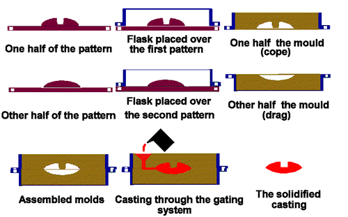
There are five steps to the sand casting process:
- Place a pattern in sand to create a mould;
- Incorporate the pattern and sand in a gating system;
- Remove the pattern;
- Fill the mould cavity with molten material;
- Allow the material to cool;
- Break away the sand mould and remove the casting.
1.1.2 Loam moulding
Loam moulding has been used to produce large symmetrical objects such as cannon and church bells. Loam is a mixture of clay and sand with straw or dung. A model of the produced is formed in a friable material (the chemise). The mould is formed around this chemise by covering it with loam. This is then baked (fired) and the chemise removed. The mould is then stood upright in a pit in front of the furnace for the molten metal to be poured. Afterwards the mould is broken off. Moulds can thus only be used once, so that other methods are preferred for most purposes.
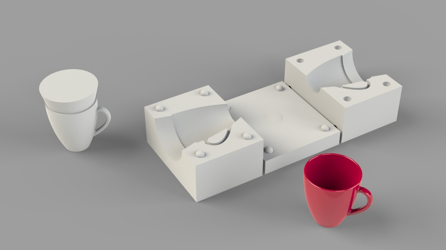
1.1.3 Plaster mould casting
Plaster casting is similar to sand casting except that plaster of paris is used instead of sand as a mould material. Generally, the form takes less than a week to prepare, after which a production rate of 1–10 units/hr-mould is achieved, with items as massive as 45 kg and as small as 30 g with very good surface finish and close tolerances.
Plaster casting is an inexpensive alternative to other moulding processes for complex parts due to the low cost of the plaster and its ability to produce near net shape castings. The biggest disadvantage is that it can only be used with low melting point non-ferrous materials, such as aluminium, copper, magnesium, and zinc.
1.1.4 Shell moulding
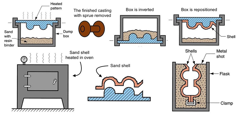
Shell moulding is similar to sand casting, but the moulding cavity is formed by a hardened "shell" of sand instead of a flask filled with sand. The sand used is finer than sand casting sand and is mixed with a resin so that it can be heated by the pattern and hardened into a shell around the pattern. Because of the resin and finer sand, it gives a much finer surface finish.
The process is easily automated and more precise than sand casting. Common metals that are cast include cast iron, aluminium, magnesium, and copper alloys. This process is ideal for complex items that are small to medium-sized.
1.1.5 Investment casting
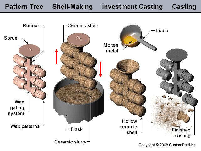
Investment casting derives its name from the fact that the pattern is invested, or surrounded, with a refractory material. The wax patterns require extreme care for they are not strong enough to withstand forces encountered during the mould making. One advantage of investment casting is that the wax can be reused.
The process is suitable for repeatable production of net shape components from a variety of different metals and high performance alloys. Although generally used for small castings, this process has been used to produce complete aircraft door frames, with steel castings of up to 300 kg and aluminium castings of up to 30 kg. Compared to other casting processes such as die casting or sand casting, it can be an expensive process. However, the components that can be produced using investment casting can incorporate intricate contours, and in most cases the components are cast near net shape, so require little or no rework once cast.
1.1.6 Evaporative-pattern casting
This is a class of casting processes that use pattern materials that evaporate during the pour, which means there is no need to remove the pattern material from the mould before casting. The two main processes are lost-foam casting and full-mould casting.
1.1.6.1 Lost-foam casting
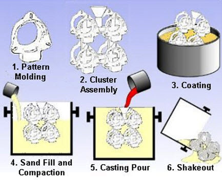
Lost-foam casting is a type of evaporative-pattern casting process that is similar to investment casting except foam is used for the pattern instead of wax. This process takes advantage of the low boiling point of foam to simplify the investment casting process by removing the need to melt the wax out of the mould.
1.1.6.2 Full-mould casting
Full-mould casting is an evaporative-pattern casting process which is a combination of sand casting and lost-foam casting. It uses an expanded polystyrene foam pattern which is then surrounded by sand, much like sand casting. The metal is then poured directly into the mould, which vaporizes the foam upon contact.
1.2 Non-expendable (permanent) mould casting
Non-expendable mould casting differs from expendable processes in that the mould need not be reformed after each production cycle. This form of casting usually results in improved repeatability in parts produced and delivers near net shape results.
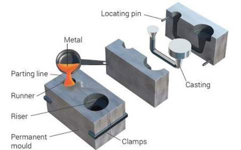
Permanent mould casting is a metal casting process that employs reusable moulds ("permanent moulds"), usually made from metal. The most common process uses gravity to fill the mould. However, gas pressure or a vacuum are also used. A variation on the typical gravity casting process, called slush casting, produces hollow castings.
Common casting metals are aluminium, magnesium, and copper alloys. Other materials include tin, zinc, and lead alloys and iron and steel are also cast in graphite moulds. Permanent moulds, while lasting more than one casting still have a limited life before wearing out.
1.2.1 Die casting (similar to injection moulding for plastics)
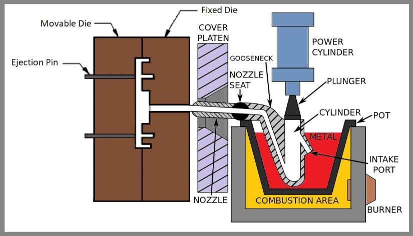
The die casting process is similar to permanent mould casting, but forces molten metal under high pressure into mould cavities (which are machined into dies). Most die castings are made from nonferrous metals, specifically zinc, copper, and aluminium-based alloys, but ferrous metal die castings are possible. The die casting method is especially suited for applications where many small to medium-sized parts are needed with good detail, a fine surface quality and dimensional consistency.
1.2.2 Semi-solid metal casting
Semi-solid metal (SSM) casting is a modified die casting process that reduces or eliminates the residual porosity present in most die castings. The process is mainly used with non-ferrous metals, such as aluminium, copper, and magnesium and combines the advantages of casting and forging. Thixotropy is the phenomenon that allows this process to work. Thixotropic fluids flow when sheared, but thicken when standing.
The two most common variants are thixocasting, rheocasting. Thixomolding and Strain-Induced Melt-Activated (SIMA) can also be considered for specific scenarios, but this document shall not expand hereupon.
SSM is done at a temperature that puts the metal between its liquidus and solidus temperature, ideally 30 to 65% solid. The mixture must have low viscosity to be usable, and to reach this low viscosity the material needs a globular primary surrounded by the liquid phase. The temperature range depends on the material and for aluminium alloys can be as much as 50 °C, but for narrow melting range copper alloys can be only several tenths of a degree.
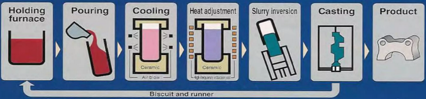
Rather than using liquid metal as the feed material, SSM casting uses a higher viscosity feed material that is partially solid and partially liquid. A modified die casting machine is used to inject the semi-solid slurry into reusable hardened steel dies. The high viscosity of the semi-solid metal, along with the use of controlled die filling conditions, ensures that the semi-solid metal fills the die in a non-turbulent manner so that harmful porosity can be essentially eliminated.
1.2.2.1 Thixocasting
Thixocasting involves injecting a semi-solid metal slurry into a mould under high pressure. The process begins with a pre-cast billet that has a non-dendritic microstructure, achieved through vigorous stirring during solidification. This billet is then reheated to a semi-solid state and injected into a die using a die-casting machine. This ensures that the metal fills the mould cavity completely, resulting in a dense, fine-grained microstructure with minimal porosity.
Thixocasting allows for the production of parts with high dimensional accuracy and tight tolerances. The process can achieve near-net-shape components, reducing the need for extensive post-processing. The exact tolerances can vary but are generally comparable to those achieved in high-pressure die casting, which can be as tight as ±0.2 mm for small parts.
1.2.2.2 Rheocasting
Rheocasting is very similar to Thixocasting, the key differences are:
- Feedstock Preparation: Thixocasting uses pre-cast billets that are reheated, while rheocasting creates the semi-solid slurry directly from molten metal.
- Cost: Rheocasting can be more cost-effective due to the use of less expensive feedstock and the ability to directly recycle the metal.
- Process Complexity: Thixocasting may require more controlled conditions for preparing the billets, whereas rheocasting can be integrated more easily into existing die-casting infrastructure.
1.2.3 Centrifugal casting
In this process molten metal is poured in the mould and allowed to solidify while the mould is rotating. Metal is poured into the centre of the mould at its axis of rotation. Due to inertial force, the liquid metal is thrown out toward the periphery. Centrifugal casting is both gravity and pressure independent since it creates its own force feed using a temporary sand mould held in a spinning chamber.
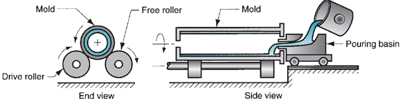
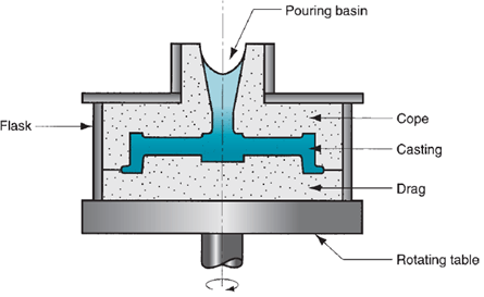
Semi-centrifugal casting is usually an expendable mould casting process instead and involves centrifugal force to produce a solid casting rather than tubular casts. The exterior regions of items formed by semi-centrifugal casting have a higher density than the centre of the rotating axis.This casting procedure makes things like spoked wheels that have rotational symmetry and can remove the casting centre. Removing the centre section of the cast also removes the cast’s lowest-density component.
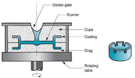
Centrifuging is also an expendable mould casting process and involves the placement of mould cavities of any shape at a certain distance from the axis of spin. The molten metal is poured from the centre, and centrifugal forces push it into the mould cavity through the sprue and the runner.
1.2.4 Rotational casting
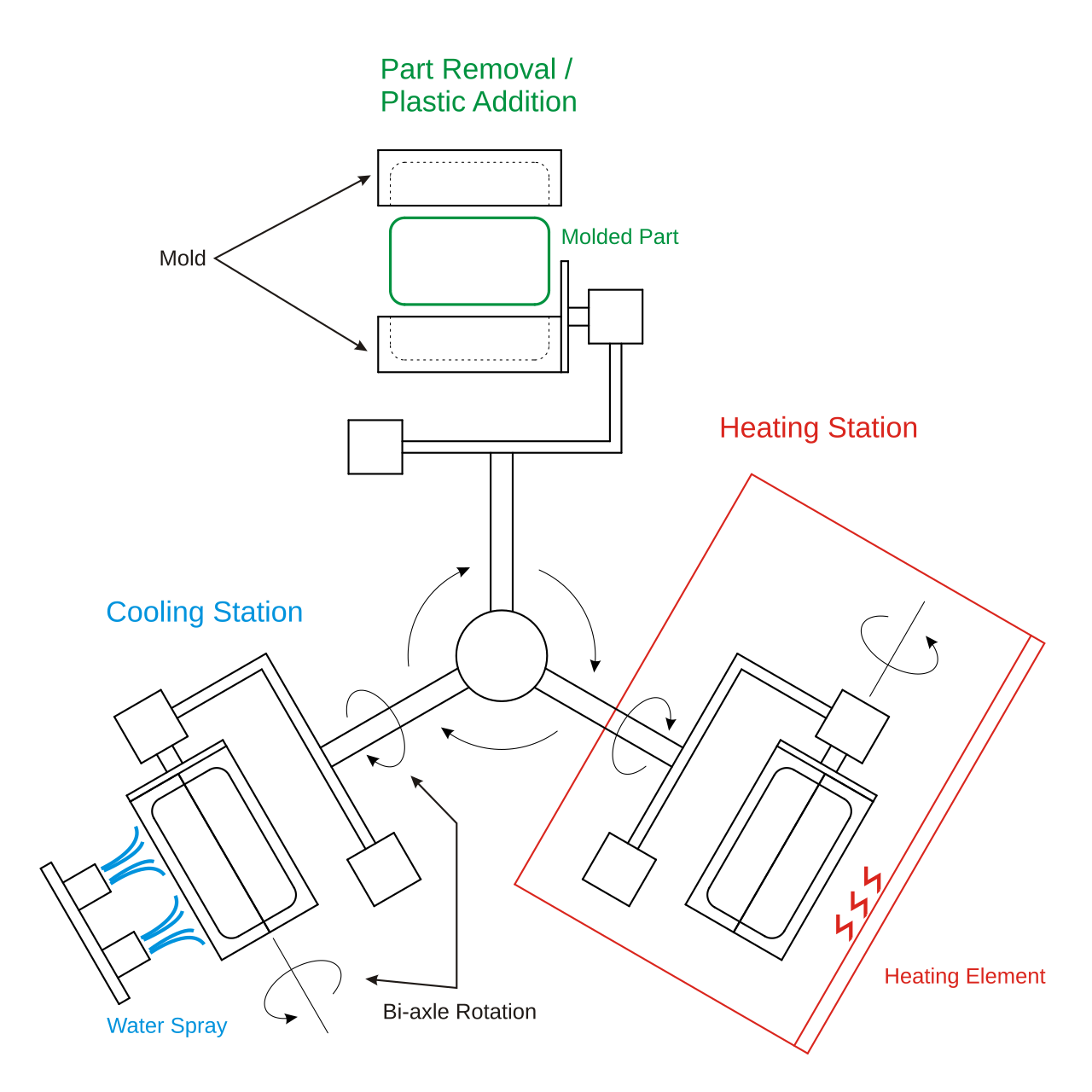
The rotational moulding process is a high-temperature, low-pressure plastic-forming process that uses heat and biaxial rotation (i.e., angular rotation on two axes) to produce hollow, one-piece parts. The rotational moulding process consists of four distinct phases:
- Loading a measured quantity of polymer (usually in powder form) into the mould.
- Heating the mould in an oven while it rotates, until all the polymer has melted and adhered to the mould wall.
- Cooling the mould, usually by fan. This stage of the cycle can be quite lengthy.
- Removal of the part.
1.2.5 Continuous casting
Continuous casting (also known as extruding) is a refinement of the casting process for the continuous, high-volume production of metal sections with a constant cross-section (also known as extruding). It's primarily used to produce a semi-finished products for further processing. Molten metal is poured into an open-ended, water-cooled mould, which allows a 'skin' of solid metal to form over the still-liquid centre, gradually solidifying the metal from the outside in. After solidification, the strand, as it is sometimes called, is continuously withdrawn from the mould.
1.2.6 Upcasting
The upcasting (up-casting, upstream, or upward casting) is a method of either vertical or horizontal continuous casting of rods and pipes of various profiles (cylindrical, square, hexagonal, slabs etc.) of 8-30mm in diameter. Copper (Cu), bronze (Cu·Sn alloy), nickel alloys are usually used because of greater casting speed.
1.2.7 Squeeze casting
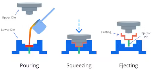
Squeeze casting combines the benefits of casting and forging to produce high-quality, near-net-shape components. Squeeze casting involves pouring molten material (typically: aluminium, magnesium, and copper alloys) into a preheated die and applying high pressure to solidify the metal. The pressure is maintained until the material fully solidifies, resulting in a dense, fine-grained microstructure with excellent mechanical properties.
1.3 Chill casting
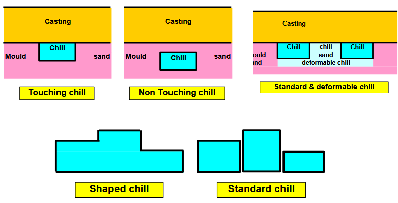
A chill is each item, which is used to decrease the temperature of the casting at its location. This is done by a high specific heat and high heat conductibility. The chill can be made of all types of materials, which must have a higher specific heat and/or conductibility as the moulding material. This can be special sand as is chromite sand, zircon sand. Or metal, as is grey or vermicular or ductile iron as in special cases copper.
There are two types of chills, depending of their location compared to the casting:
- External chills: where the chill is located at the surface of the casting (either in contact with the casting, or non-touching).
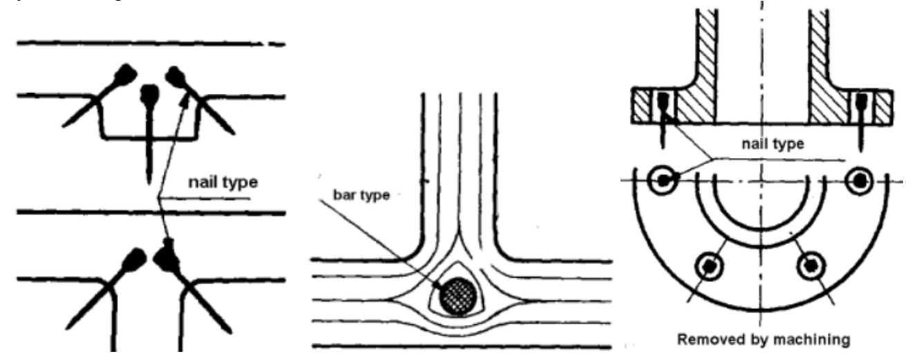
- Internal chills: where the chill is located inside the casing and becomes part of the casting. Most of the quality standards do not allow non-melted chills (or inserts). It must be of equal material to the casting.
Design considerations
This chapter explains what to take into account when designing parts for casting.
2.1 Draft angle
Include draft angles on all surfaces perpendicular to the parting line to facilitate easy removal of the pattern from the mould. The draft angle allows the pattern to be extracted without damaging the mould. Stripping is much easier when a draft angle is provided.
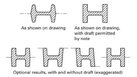
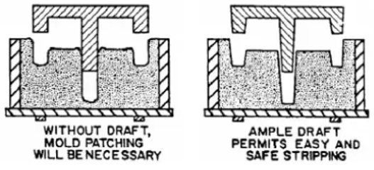
A typical draft angle is 1°, nominal is 2°. More draft aids ejection, but may generate a material mass on sections contained in one side of the mould.
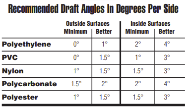
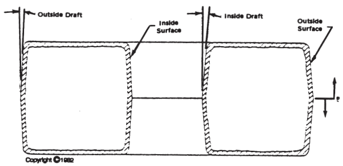
Textured surfaces on a part can be achieved by providing the reverse details to the mould. Parts that incorporate special finishes of this type shall be designed with proportionally greater draft angles. A rule of thumb is to add 1° of draft angle for every 25 microns of texture depth.
2.2 Parting line
A part should be oriented in a mould so that the large portion of the casting is relatively low and the height of
the casting is minimized. In general the parting line should be along a flat plane rather than contoured. The parting line should be placed as low as possible relative to the casting for less dense materials (even for aluminium alloys) and located at around the mid height for denser materials (such as steels).
The parting line should be positioned to avoid critical surfaces and, to lesser importance, to minimize the visibility.
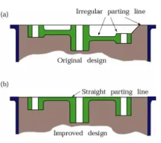
Additionally, features must be kept in the parting plane to simplify the part, when a stepped parting line is required allow a shut-off angle of 7°. Minimum shut off angle is 5°.
2.3 Wall thickness
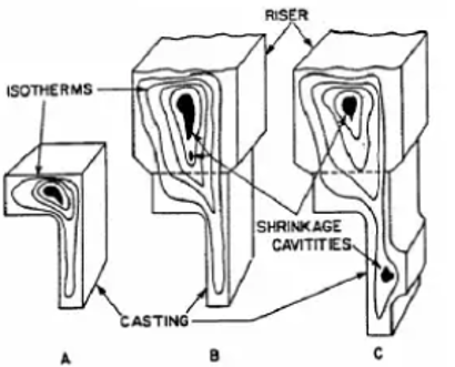
Use a constant uniform wall thickness (if possible). This is essential as the material shrinks as it cools. This means that the geometry must allow for even cooling/shrinkage otherwise there is a chance that cavities form. Ideally, the wall thickness should be uniform and equal to the nominal wall thickness.
Proper riser design also has a large influence on the prevention of shrinkage cavities (at the top of the part).
For rotational moulding it is best practice to specify the nominal wall thickness and the minimum allowable wall thickness that can exist anywhere on the finished part. Depending on the part’s size and shape and the material being moulded, a commercially acceptable wall thickness tolerance of ±20% is usually possible. A wall thickness specification of ±10% is considered to be a precision tolerance that could be achieved only with added cost and difficulty.
Rotationally moulded parts usually contain gradually thickening walls on the outside corners and slightly thinner walls on the sharp inside corners. Because of this fact, wall thickness tolerances are usually understood to refer to the nominal wall only, and not the corners of the part.
2.3.1 Metals
| Process | Material | Minimum wall thickness [mm] | Typical wall thickness [mm] |
|---|---|---|---|
| Sand casting | Aluminium alloys | 3 – 5 | 4 – 12 |
| Cast iron | 4 – 6 | 5 – 25 | |
| Steel | 5 – 8 | 6 – 30 | |
| Copper alloys | 3 – 5 | 4 – 15 | |
| Investment casting | Aluminium alloys | 1.5 – 2.5 | 2 – 6 |
| (Stainless) Steel | 1.5 – 3 | 2 – 10 | |
| Copper alloys | 1.5 – 2.5 | 2 – 8 | |
| Die casting | Aluminium alloys | 0.8 – 1.5 | 1 – 5 |
| Zinc alloys | 0.5 – 1 | 0.8 – 3 | |
| Magnesium alloys | 0.8 – 1.5 | 1 – 4 |
2.3.2 Plastics
| Process | Resin | Recommended wall thickness [mm] |
|---|---|---|
| Injection molding | ABS | 1.15 – 3.5 |
| Acetal | 0.75 – 3 | |
| Acrylic | 0.65 – 4 | |
| Liquid crystal polymer | 0.75 – 3 | |
| Long-fiber reinforced plastics | 1.91 – 25 | |
| Nylon | 0.75 – 3 | |
| Polycarbonate | 1 – 4 | |
| Polyester | 0.65 – 3 | |
| Polyethylene | 0.75 – 5 | |
| Polyphenylene sulfide | 0.5 – 4.5 | |
| Polypropylene | 0.9 – 3.8 | |
| Polystyrene | 0.9 – 3.8 | |
| Polyurethane | 2 – 19 | |
| Rotational molding | 2 – 8 |
2.3.3 Wall junction design
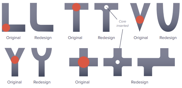
Wall junctions are usually accompanied by a non-uniform section. In the image below you can see different junctions and possible alternative design solutions to keep the cross section (mostly) uniform:
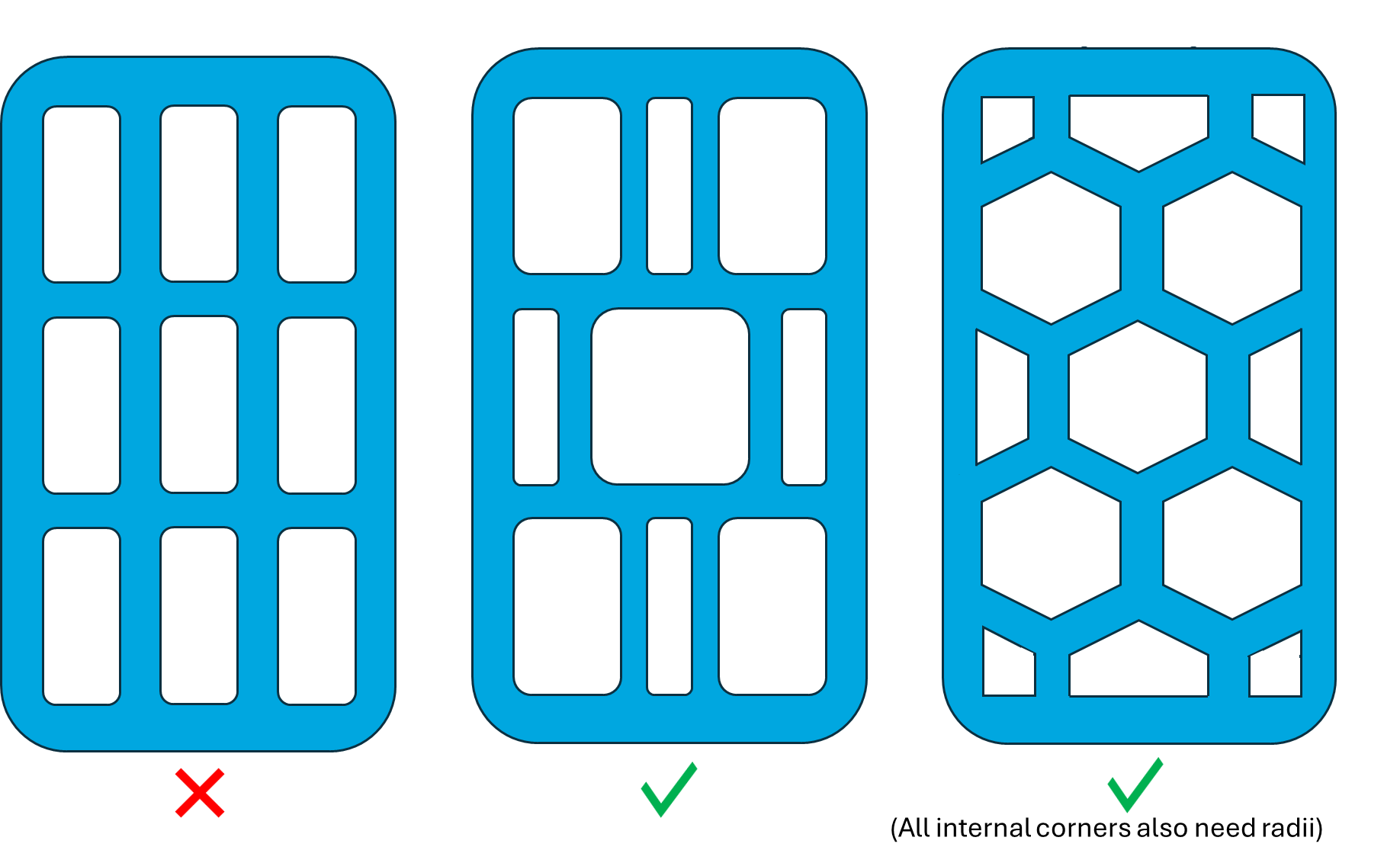
Another example to avoid the use of x-junctions to prevent cracking during cooling:
2.3.4 Wall thickness variation
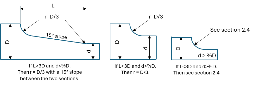
If it is not possible to keep a uniform wall thickness, make sure that the transition is as smooth as possible using a chamfer or a fillet with a length that is at least 3 times the difference in thickness.
An alternative method to deal with inconsistent wall thickness is to apply a chill to locally increase the cooling rate to prevent shrinkage cavities.
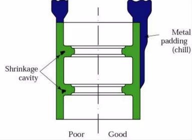
2.3.5 Wall separation (rotational molding)
For rotational moulding, a separation between parallel walls of five times the nominal wall thickness of the part is preferred. Wall separations of as little as three times the nominal wall thickness have been moulded successfully, with only an occasional bridging over.
2.4 Corner fillets/radii
Use generous fillet radii on inside and outside corners to reduce stress concentrations and improve metal flow. Sharp corners and edges should be avoided as they can lead to defects and reduced part strength.
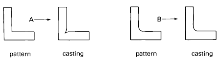
The size of corner radii is a function of the material, process and wall thickness.
The wall thickness matters as thicker walls cool/solidify slower, so larger radii help prevent defects like shrinkage or cracking. Thinner walls require smaller radii to maintain flow and avoid weak spots.
Note: in visible areas that require a high surface finish, work with higher-order fillets! This minimizes the visibility of the transition.
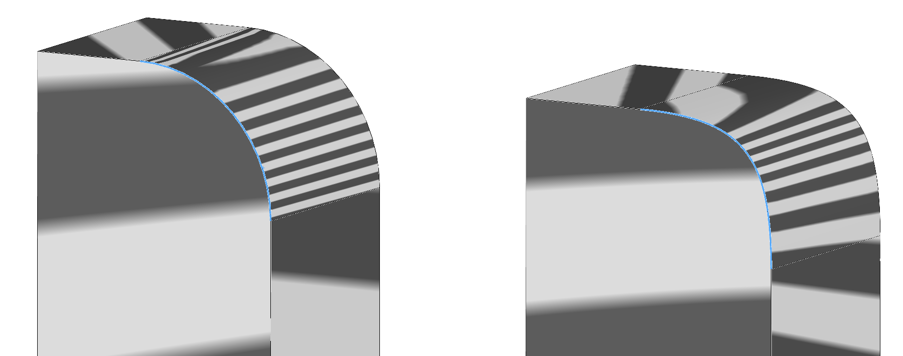
The following sections show guideline sizing for the corner fillets/radii.
2.4.1 Metals
| Process | Corner location | Guideline |
|---|---|---|
| Sand casting | Internal | 0.5 - 1 times the wall thickness. (Min. 3.2 mm) |
| External | 1 - 2 times the wall thickness. (Min. 3.2 mm) | |
| Investment casting | Internal | > 0.3 times the wall thickness. (Make as large as possible) |
| External | > 0.5 times the wall thickness. (Make as large as possible) | |
| Die casting | Internal | 0.25 - 0.5 times the wall thickness |
| External | 0.5 - 1 times the wall thickness |
Steel castings: use the lower end of the range to reduce uneven cooling rates due to the limited heat transfer coefficient.
Elastomers: can use smaller radii (0.25–0.5 × wall thickness).
2.4.2 Plastics
| Process | Corner location | Guideline |
|---|---|---|
| Injection moulding | Internal | 0.5 - 1 times the wall thickness |
| External | Internal corner radius + material thickness leading to 1-1.5 times the wall thickness | |
| Rotational moulding | Internal (Polyethylene) | Minimum = 1.5 mm, Commercial = 4.75 mm, Ideal = 6.5 mm |
| Internal (Polyvinylchloride) | Minimum = 3 mm, Commercial = 6.5 mm, Ideal = 9.5 mm | |
| Internal (Nylon) | Minimum = 4.75 mm, Commercial = 9.5 mm, Ideal = 19 mm | |
| Internal (Polycarbonate) | Minimum = 3 mm, Commercial = 9.5 mm, Ideal = 12.5 mm | |
| External (Polyethylene) | Minimum = 3 mm, Commercial = 4.75 mm, Ideal = 6.5 mm | |
| External (Polyvinylchloride) | Minimum = 2 mm, Commercial = 4.75 mm, Ideal = 6.5 mm | |
| External (Nylon) | Minimum = 4.75 mm, Commercial = 9.5 mm, Ideal = 12.5 mm | |
| External (Polycarbonate) | Minimum = 6.5 mm, Commercial = 9.5 mm, Ideal = 19 mm |
Fiber filled plastics: use the upper end of the range to reduce stress concentration.
Elastomers: can use smaller radii (0.25–0.5 × wall thickness).
2.4.3 Corner angle
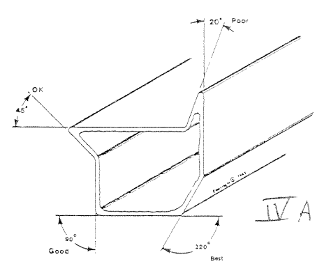
For rotational molding, corner angles of less than 90° begin the require greater care and attention by the molder. Corner angles of 45° can be produced on parts which are molded in polyethylene, polyvinylchloride, and nylon, but they are more difficult to achieve with the harder flow materials such as polycarbonate.
The minimum recommended angle for polyethylene and polyvinylchloride is 30°, for nylon it is 20°, and for materials like polycarbonate it is 45°. Please be aware that an inside corner radius is required.
Corner angles that are less than those recommended result in parts which are not completely filled out.Leading to increased porosity and increased risk of rejects.
2.5 Supports/Ribs
When even the maximum recommended wall thickness is not enough to meet the functional requirements of a part, ribs can be used to improve its stiffness/strength. Ribs can also be used to improve material feeding or to reduce the weight of a part (might allow for a smaller cross section).
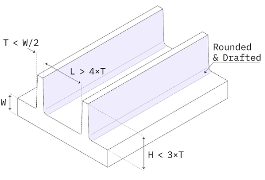
- Rib Thickness: the thickness of a rib should be between 50% and 75% of the nominal wall thickness it supports.
- Rib height: the height of a rib should be smaller than 3 times its thickness.
- Rib Spacing: to avoid creating thin mold walls that can reduce mold life, the distance between ribs should be at least two and a half times the nominal wall thickness for metal parts, which means 4 times its own thickness.
- Blending: Ribs should be blended with fillets and radii where they meet the nominal wall to prevent stress concentrations and improve material flow.
Additionally, the base of vertical features (like ribs, bosses, snap-fits) must always be rounded (see section 2.4).
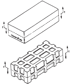
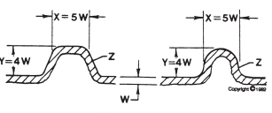
Rotational moulding ribs are shown in Figure 31. Good average proportions for rotationally moulded
stiffening ribs are shown in Figure 32 where the depth (Y) of the rib is at least four times the nominal wall thickness (W) and the width (X) is at least five times the nominal wall thickness.
Like every surface of a casting part, the side walls (Z) shall be provided with tapers to improved their release from the cavity.
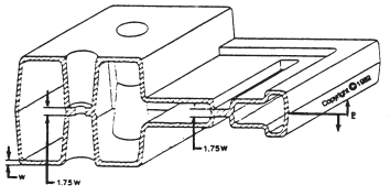
Kiss-off ribbing is a unique capability of the rotational moulding process. With this form of reinforcement, two closely spaced walls are attached to each other to provide added strength and dimensional stability. The thickness in the kiss-off area is usually established by the trial and error method; however, 175% of the nominal wall thickness (W) is a good starting point.
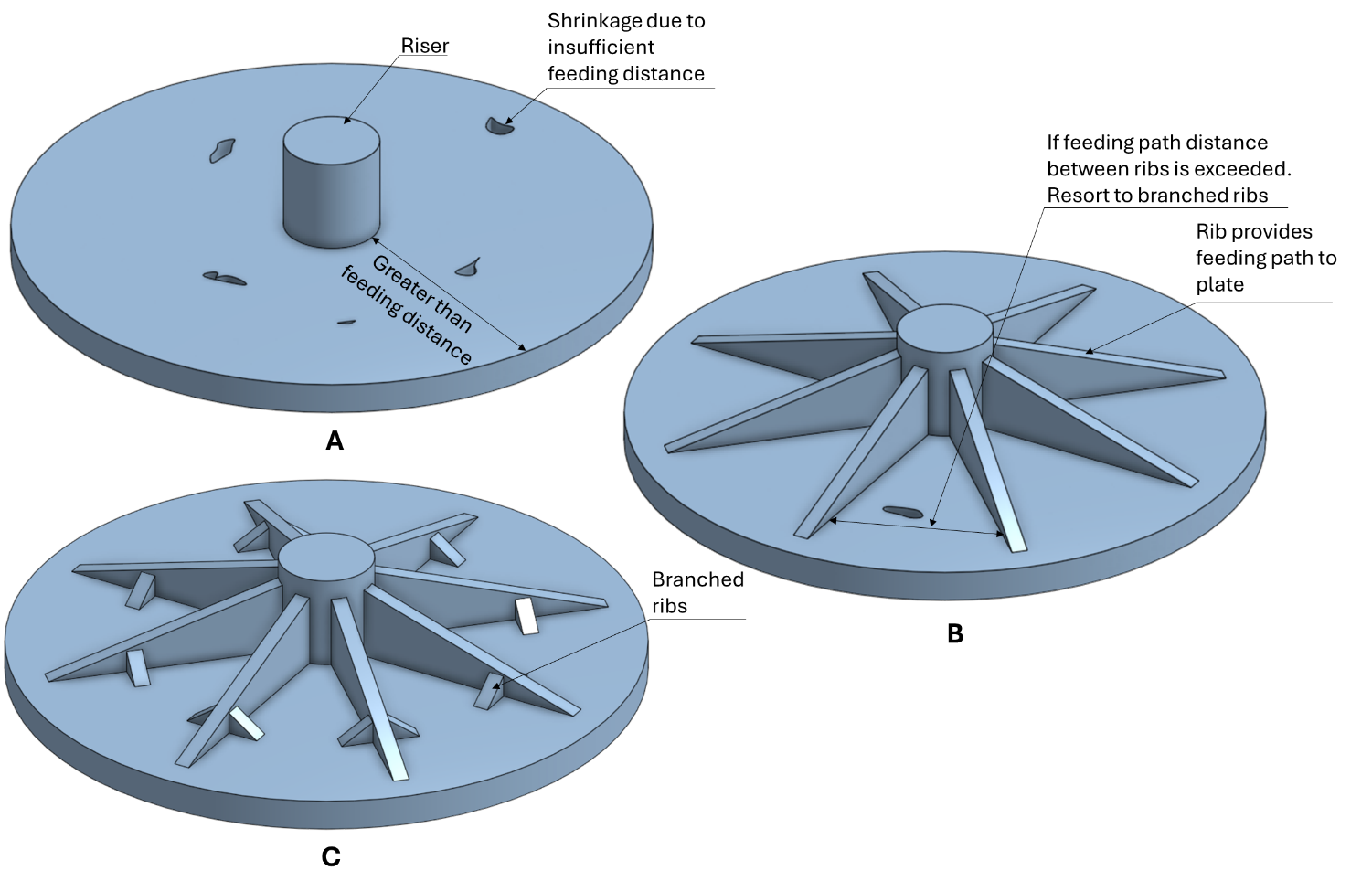
Feeding path design considerations are shown in figure 34: (a) Circular plat plate with a single riser. (b) Addition of wedge shaped ribs to ensure proper solidification. (c) Branched ribs to overcome feeding problems at the circumference of the plate.
2.6 Bosses and holes (for fasteners/alignment)
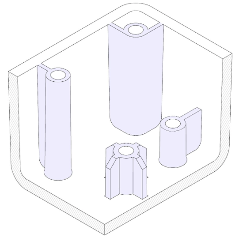
Bosses are very common in Injection Molded parts and are used as points for attachment or assembly. They consist of cylindrical projections with holes designed to receive screws, threaded inserts, or other types of fastening and assembly hardware. A good way to think of a boss is as a rib that closes on itself in a circle.
The ideal design for a boss is one that is reinforced with ribs or gussets for added strength, rather than simply making the boss itself thicker. The base of a boss should be radiused where it meets the nominal wall to reduce stress concentrations.
The design of bosses, holes, and pockets is a key consideration, as they require the use of cores to form the cavity. A core is a (separate) piece of the mold that forms an internal feature. The minimum size of a core is dependent on the material thickness surrounding it, the length of the core, and the process used by the supplier.
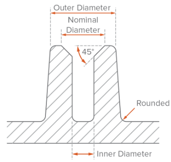
If treads are needed they should be added afterwards by means of machining or inserts.
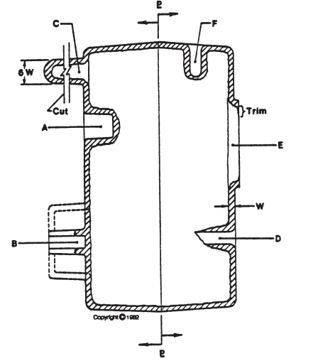
The following hole types can be made with rotational moulding:
A. Blind hole.
B. Outwardly projecting blind hole, not recommended as the plastic will not flow down in the restricted walls around the core pin.
C. Outwardly projecting through hole, made by cutting off the tip after moulding. The inside diameter of these holes cannot be controlled as well as those shown by the letter A.
D. Through hole, produced by the use of a vent tube or by mounting a long core pin.
E. Large hole through the wall, can be produced similarly to holes indicated by the letter D. These are made by a part of the cavity that has insufficient heat for the plastic to adhere to it. A small amount of plastic will usually creep a short distance into the hole, this is trimmed afterwards.
F. Blind hole parallel to the parting line of the part. These can be made similarly to undercuts. Avoid to keep the cost low.
2.7 Undercuts
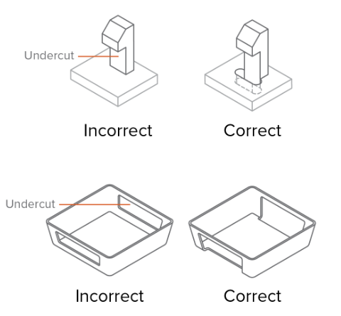
The simplest mold (the straight-pull mold) consist of 2 halves. Features with undercuts (such as the teeth of a thread or the hook of a snap-fit joint) may not be manufacturable with a straight-pull mold though. This is either because the mold cannot be CNC machined or because the material is in the way of ejecting the part.The teeth of a thread or the hook of a snap-fit joint are examples of undercuts.
Avoiding undercuts altogether might be the best option. Undercuts always add cost, complexity, and maintenance requirements to the mold. A clever redesign can often eliminate undercuts.
The following sub-sections show methods to deal with undercuts if avoiding them is not possible.
2.7.1 Shut offs
Shut-offs are a useful trick to deal with undercuts on internal regions of the part (for snap-fits) or on the sides of the part (for holes or handles).Below are some examples of how moulded parts can be redesigned to avoid undercuts: essentially, material is removed in the area under the undercut, eliminating the issue altogether by letting part of the mould occupy the space and thus supporting the undercut.
2.7.2 Move the parting line
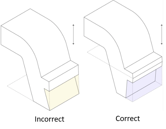
The simplest way to deal with an undercut is to move the parting line of the mold to intersect with it.
This solution is suitable for many designs with undercuts on an external surface. Don’t forget to adjust the draft angles accordingly.
2.7.3 Use a stripping undercut (bumpoff)
Stripping undercuts (also known as bumpoffs) can be used when the feature is flexible enough to deform over the mold during ejection. Stripping undercuts are used to manufacture the threads in bottlecaps.
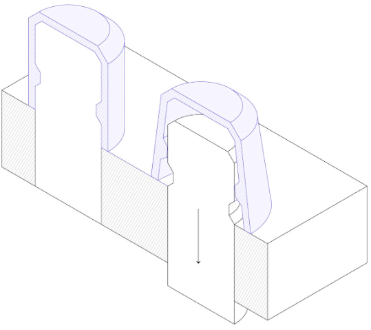
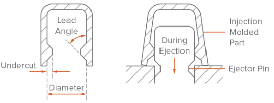
Bumpoffs can only be used under the following conditions:
• The stripping undercut must be located away from stiffening features, such as corners and ribs.
• The undercut must have a lead angle of 30° to 45° degrees.
• The injection molded part must have space and must be flexible enough to expand and deform.
It is recommended to avoid stripping undercuts in stiffer materials. Typically, flexible plastics such as PP, HDPE or Nylon (PA) can tolerate undercuts of up to 5% of their diameter.
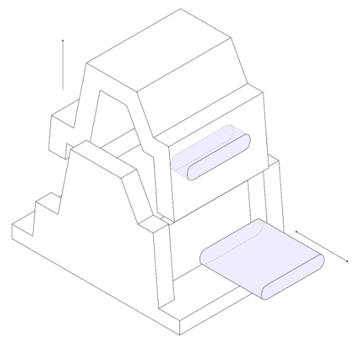
2.7.4 Sliding side-actions and cores
Sliding side-actions and cores are used when it is not possible to redesign the injection molded part to avoid undercuts. Side-action cores are inserts that slide in as the mold closes and slide out before it opens. Keep in mind that these mechanisms add cost and complexity to the mold.
Follow these guidelines when designing a side actions:
• There needs to be for the core to move in and out. This means that the feature must be on the other side of the part.
• The side-actions must move perpendicularly. Moving at an angle other than 90° is more complicated, increasing cost and lead times.
• Don’t forget to add draft angles to your design as usual, taking in consideration the movement of the side action core.
2.7.5 Rotational moulding undercuts
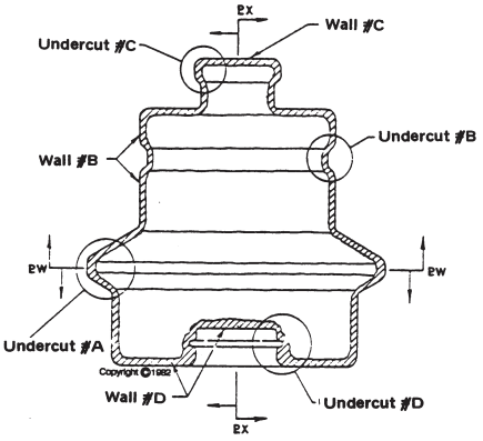
An undercut in a rotationally moulded part is any inwardly or outwardly projecting wall that is parallel to the parting line which must be deformed in order to be removed from the mould.
The part below contains four different types of undercuts:
A. Can be avoided by moving the parting line to line W-W or X-X.
B. Can be avoided by moving the parting line to line X-X, whether or not it can be stripped from the mould is dependent upon the flexibility of the material, the depth of the undercut, the shape of the undercut, and the location in relation of the undercut in relation to the surrounding walls.
C. Is similar to undercut , but more difficult to remove due to the wall #C reinforcing the undercut.
D. Internal undercuts like this should be avoided where possible. When necessary, keep the depth to a minimum and use flexible or semi-rigid plastic materials only.
2.8 Machining after casting
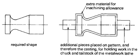
Before making the pattern it is important to consider whether the finished casting will need to be machined. The surfaces which require machining will, of course, have to be left thicker, so that material can be removed when machining without reducing the desired final shape.
2.9 Risers/venting
The position of the downgate and risers will invariably depend upon the shape of the casting. Sometimes the riser can be placed directly on the casting to counter the shrinkage which can be noticeable on thick sections.
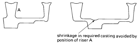
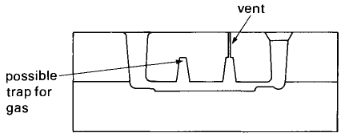
Even though a riser is used, it is still necessary to vent the top-part box (cope) to help the gases escape. It is safer to vent the top-part whilst the riser and downgate pegs are still in position. If they are taken out, the mould is weaker and could crack when being vented.
Any areas within the mould which are potential traps for evolved gases should be vented.
2.10 Runner bar
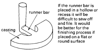
As with the riser and downgate pegs, the position of the runner bar will depend upon the shape of the casting. However, care should be taken to make sure that its removal after casting is not made difficult by poor positioning.
2.11 Tolerances
The ISO 8062-3 standard defines Dimensional Casting Tolerance (DCT) grades from CT1 to CT16, where lower numbers indicate a tighter, more precise tolerance.
| Tolerance grade | Process | Typical tolerance range |
|---|---|---|
| CT1-CT4 | High-precision die casting | ±0.05% - 0.3% of dimension |
| CT5-CT9 | Investment casting / shell moulding | ±0.1% - 0.8% of dimension |
| CT10-CT14 | Sand casting | ±0.4% - 2% of dimension |
| CT15-CT16 | Very-large / Non-critical castings | ±2.5% - 3.5% of dimension |
Table 1 – Dimensional Casting Tolerance (DCT) according to ISO 8062-3
| Material(s) | Flatness Tolerance |
|---|---|
| Polyethylene, Polyvinylchloride | Precision = ± 0.01 mm/mm Commercially acceptable = ± 0.02 mm/mm Ideal = ± 0.05 mm/mm |
| Nylon, Polycarbonate | Precision = ± 0.003 mm/mm Commercially acceptable = ± 0.005 mm/mm Ideal = ± 0.01 mm/mm |
Table 2 – Rotational moulding flatness tolerances
It is best practice to avoid flat panels when using hollow molds. An alternative design solution for rotational moulded parts can be seen in Figure 31.
Defects (to check for)
Common defects to check for are:
- Misruns: a misrun is a casting that has solidified before completely filling the mould cavity. Typical causes include: fluiditiy of the molten material is insufficient, pouring temperature is too low, pouring is done too slowly, cross section of the mould cavity is too thin.
- Cold shuts: a cold shut occurs when two portions of the material flow together, but there is a lack of fusion between them due to premature freezing. It’s causes are similar to those of a misrun.
- Cold shots: when splattering occurs during pouring, solid globules of the material are formed that become entrapped in the casting. Pouring procedures and gating system designs that avoid splattering can prevent these defects.
- Shrinkage cavities: this defect is a depression in the surface or an internal void in the casting caused by solidification shrinkage that restricts the amount of the molten material available in the last region to freeze. It often occurs near the top of the casting in which case it is referred to as a pipe.
- Microporosity: this refers to a network of small voids distributed throughout the casting caused by localised solidification shrinkage of the final molten material in the dendritic structure.
- Hot tearing: this defect, also known as hot cracking, occurs when the casting is restrained or in the early stages of cooling after solidification. The defect is manifested as a separation of the material at a point of high tensile stress caused by the material’s inability to shrink naturally.
- Alignment errors: these occur when the mould halves or cores are not properly aligned, leading to dimensional inaccuracies, mismatched surfaces, or offset features in the final casting.
- Bad quality material: defects can arise from impurities, incorrect alloy composition, or contaminated raw materials. This can result in weak mechanical properties, inclusions, or inconsistent solidification.
- Inclusions: foreign particles, such as slag, sand, or oxides, become trapped in the molten metal and remain in the casting. These inclusions weaken the casting and can act as stress concentrators.
- Gas porosity: this defect is caused by trapped gases in the molten metal, resulting in bubbles or voids in the casting.
- Surface defects: these include rough surfaces, fins, or flash, which are often caused by poor mould quality, improper clamping, or excessive metal pressure.
Table of References
| Reference | Purpose |
|---|---|
| Injection molding | Injection molding |
| Zinc casting | Zinc casting |
| The introductory guide to designing rotationally molded plastic parts | Rotation moulding design guidelines |