

Document Goal
Goal: Informing engineers of the limitations and guidelines for the design of parts to be produced by additive manufacturing. This document provides designers with background information and guidelines on additive manufacturing. There are two main parts: additive manufacturing background information, and general rules and guidelines.
Additive Manufacturing Background Information
Additive manufacturing (AM), also known as 3D printing, creates three-dimensional objects layer by layer. Unlike traditional subtractive methods – turning, milling, grinding and similar – that remove material from a starting shape, AM builds parts only where material is needed.
There are seven primary process categories as defined by ISO/ASTM 52920:
- Material extrusion (FDM / FFF)
- Vat Photopolymerization (SLA / DLP)
- Powder Bed Fusion (SLS / DMLS / SLM / EBM / SHS)
- Material Jetting
- Binder Jetting
- Directed Energy Deposition
- Sheet Lamination
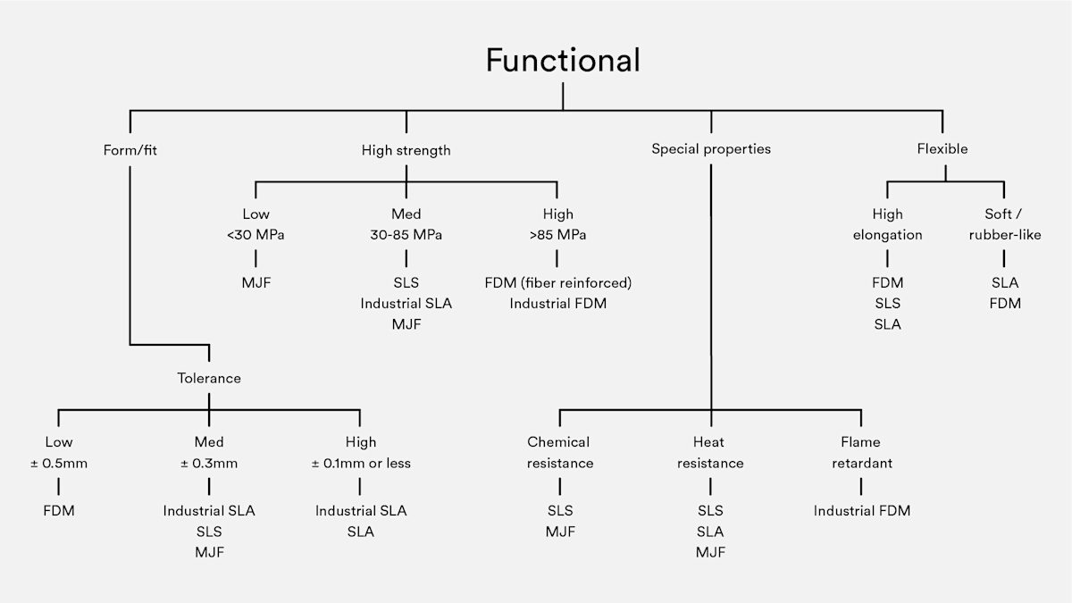
The main differences between processes lie in the way layers are deposited and in the materials used. Each method has its own advantages and drawbacks. The jetting processes (Material Jetting, Binder Jetting, and Multi Jet Fusion) are grouped together in this document.
1.1 Material Extrusion (FDM / FFF)
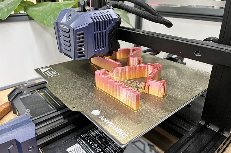
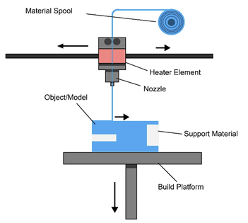
In fused deposition modelling (FDM), also known as fused filament fabrication (FFF), material is drawn through a heated nozzle and deposited layer by layer. The nozzle moves in the horizontal plane while the build platform lowers vertically after each layer. FDM is the most widely used technique and is common on desktop and industrial printers alike.
FDM requires support structures wherever the material is not directly resting on the workpiece or build platform. A more recent variant – fused particle fabrication (FPF), sometimes called fused granular fabrication (FGF) – prints directly from pellets, enabling the use of recycled materials and reducing material cost.
The process of 3D printing directly from pellets to avoid the conversion to filament is called fused particle fabrication (FPF) (or fused granular fabrication (FGF)) and has the potential to use more recycled materials.
1.2 Vat Photopolymerisation
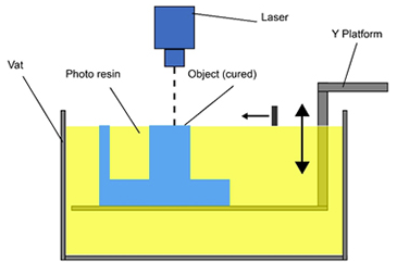
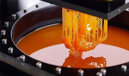
Vat photopolymerisation uses a vat of liquid, UV-sensitive polymer resin that hardens on exposure to light. The two most common variants, SLA and DLP, are both described below. Because the process builds in liquid, no structural support exists during the build phase and support structures must be added in the same way as for FDM.
1.2.1 Stereolithography (SLA)
SLA is the second most widely used 3D printing technique. It produces highly accurate, isotropic and watertight parts with smooth surfaces and fine details. Feature sizes down to 0.1 mm are readily achievable; certain specialised machines can reach 0.02 mm.
An SLA printer selectively exposes liquid resin to a laser beam. The resin cures only where the laser is focused; the remaining liquid is washed away after printing. Resolution in the XY plane depends on the laser spot size (typically 30–140 µm, non-adjustable). Vertical resolution (Z) ranges from 25 to 200 µm – a trade-off between print speed and surface quality. For comparison, a desktop FDM printer typically works at 150–400 µm per layer.
After printing, the part must be washed with ethanol or a similar solvent to remove uncured resin, then UV post-cured to fully harden the material and improve mechanical stability. Two-directional laser exposure is also possible on certain systems, further increasing resolution.
1.2.2 Digital Light Processing (DLP)
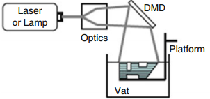
DLP also falls under vat photopolymerisation. The key difference is the light source: DLP uses a digital projector (Digital Micromirror Device) that flashes an image of the entire layer at once, making it generally faster than SLA for single-part builds.
One drawback of DLP is that output quality decreases when printing multiple parts in a single tray, because the fixed pixel grid is spread over a larger area. SLA, which traces geometry with a focused laser, does not share this limitation.
1.3 Powder Bed Fusion
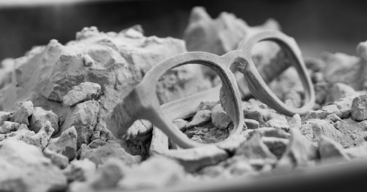
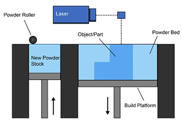
Powder Bed Fusion (PBF) encompasses several processes that use a laser or electron beam to melt and fuse material powder layer by layer. A roller or blade spreads fresh powder over each completed layer. The surrounding unfused powder acts as a support medium, removing the need for dedicated support structures – a major advantage over FDM and SLA.
PBF step by step:
- A layer – typically 0.1 mm – of material powder is spread over the build platform.
- A laser (or electron beam) fuses the cross-section of the model in that layer.
- A new layer of powder is spread over the previous one.
- Subsequent cross-sections are fused and added.
- The process repeats until the full model is complete. Loose, unfused powder is removed after the build.
The Powder Bed Fusion process includes the following commonly used printing techniques:
1. Selective laser sintering (SLS)
2. Direct metal laser sintering (DMLS)
3. Selective laser melting (SLM)
4. Electron beam melting (EBM)
5. Selective heat sintering (SHS)
1.3.1 Selective Laser Sintering (SLS) – polymers
SLS machines use a laser to sinter polymer powder layer by layer. The build chamber is held a few degrees below the material melting point, reducing the energy the laser needs to fuse each layer. The chamber is typically filled with nitrogen to limit oxidation and improve part quality. Parts require a cool-down period after the build to achieve high dimensional accuracy.
1.3.2 Direct Metal Laser Sintering (DMLS) – metals
DMLS follows the same process as SLS but uses metal powders instead of polymers. A wide range of engineering alloys is available. The powder is sintered layer by layer, producing functional metal parts with good mechanical properties.
1.3.3 Selective Laser Melting (SLM) – metals
SLM is similar to DMLS but fully melts the powder rather than sintering it, typically yielding higher density parts. It generally builds faster than SLS but requires an inert gas atmosphere, has higher energy consumption and an energy efficiency in the range of 10–20 %. A roller or blade spreads each new powder layer; blade-based systems often vibrate the blade to improve powder distribution.
1.3.4 Electron Beam Melting (EBM) – metals
EBM fuses metal powders using an electron beam controlled by electromagnetic coils, operating in a vacuum. The even temperature distribution during fusion results in very good strength properties, making EBM well suited for high-performance applications in aerospace and medical implants. Compared to conventional CNC machining of titanium, EBM at a 0.1 mm layer thickness can achieve comparable results in shorter lead times and with cost savings of up to 35 %.
1.3.5 Selective Heat Sintering (SHS)
SHS uses a heated thermal print head rather than a laser to fuse thermoplastic powder. This significantly reduces the heat and power levels required. SHS is primarily used for concept prototypes. A typical desktop SHS machine provides a build volume of approximately 200 × 160 × 140 mm with a layer thickness of 0.1 mm.
1.4 Jetting Processes
The jetting process family consists of three main categories: Material Jetting, Binder Jetting, and Multi Jet Fusion.
1.4.1 Material Jetting (PolyJet)
Material Jetting creates parts in a method analogous to a two-dimensional inkjet printer. Liquid photopolymer or wax is jetted onto the build platform via a continuous or Drop-on-Demand (DOD) approach, cured layer by layer under UV light. Support structures are printed simultaneously from a dissolvable material.
Material Jetting step by step:
- The print head is positioned above the build platform.
- Droplets of material are deposited onto the required areas using thermal or piezoelectric actuation.
- Droplets solidify and form the first layer.
- Subsequent layers are built up on top.
- Layers are allowed to harden or are cured by UV light; support material is removed in post-processing.
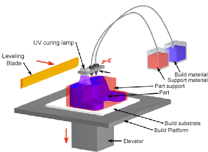
Material Jetting produces near-homogeneous parts with excellent surface finish and is the main process enabling multi-material printing in a single build. Its key limitation is that parts are typically brittle and have poor mechanical properties compared to FDM or PBF, making it best suited to prototyping and visual models.
1.4.2 Binder Jetting
Binder Jetting uses a powder-based material (polymers, metals, ceramics, or glass) and a liquid binder that acts as an adhesive between powder layers. A print head moves in the horizontal plane, depositing alternating layers of powder and binder. After each layer the build platform lowers by one layer thickness. No support structures are required because the surrounding powder supports the part throughout the build.
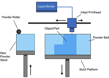
After printing, parts are in a fragile green state and require a post-processing step before they can be used:
- Infiltration: the part is placed in a furnace to burn out the binder, leaving roughly 60 % porosity. Bronze is then infiltrated by capillary action, resulting in approximately 10 % porosity and good mechanical strength.
- Sintering: the binder is similarly burnt out and the remaining metal particles are bonded together at high temperature, yielding less than 3 % porosity.
Both post-processing routes cause significant shrinkage: parts up to 75 mm typically shrink 0.8–2 %; larger parts average around 3 %. Non-uniform shrinkage must be accounted for in collaboration with the supplier. Even after post-processing, internal porosity remains – approximately 90 % density after infiltration and 97 % after sintering – so mechanical properties are generally inferior to fully dense DMLS/SLM parts.
Full-colour Binder Jetting is possible by simultaneously jetting ink and binder onto plaster or PMMA powder. The parts are subsequently coated with cyanoacrylate infiltrant and optionally an epoxy layer to improve strength and colour vibrancy. These full-colour parts are very brittle and not recommended for functional use.
1.4.3 Multi Jet Fusion (MJF)
MJF shares similarities with Binder Jetting – both deposit powder layer by layer and jet agents onto it – but works fundamentally differently. Binder Jetting uses a single adhesive binder to bind the powder layers together. MJF uses two agents: a fusing agent defining where material will melt and a detailing agent precisely defining part edges. Together, they cause the polymer chains within the material to entangle and fuse, rather than just bind, producing isotropic, functional parts with properties more comparable to injection-moulded components.
1.5 Directed Energy Deposition
Directed Energy Deposition (DED) is primarily used to repair existing components or to add material features onto near-net-shape parts. It also covers a range of related processes known under various industry names: laser engineered net shaping, directed light fabrication, direct metal deposition, and 3D laser cladding.
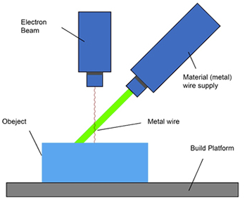
DED forms 3D geometries by melting material as it is deposited, using a focused energy source – laser, electron beam, or plasma arc – through a nozzle mounted on a multi-axis arm. The material is supplied in wire or powder form.
DED step by step:
- A 4- or 5-axis arm with a deposition nozzle moves around or above the target object.
- Material (wire or powder) is fed through the nozzle onto the existing surface.
- The energy source melts the material upon deposition.
- Successive layers solidify and build up new geometry on the substrate.
1.5.1 Laser Metal Deposition (LMD)
LMD uses a high-power laser to melt metal powder or wire feedstock. It offers high precision, excellent surface finish, and the ability to deposit a wide range of alloys. LMD is well suited for adding local features (ribs, bosses, wear pads), rebuilding worn surfaces, and applying corrosion- or wear-resistant cladding layers.
1.5.2 Electron Beam Additive Manufacturing (EBAM)
EBAM uses an electron beam as the heat source and typically processes wire feedstock in a vacuum chamber. It is particularly suited to reactive and high-temperature alloys – titanium, nickel-based superalloys – where oxidation must be avoided. Deposition rates are high, often several kilograms per hour, making EBAM attractive for large structural components. All fixtures and components must be compatible with the vacuum environment.
1.6 Sheet Lamination
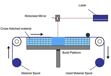
Sheet lamination processes bind and cut successive layers of sheet material to build a 3D object. The two main variants are Ultrasonic Additive Manufacturing (UAM) and Laminated Object Manufacturing (LOM).
UAM uses metal foils (aluminium, copper, stainless steel, titanium) bonded by ultrasonic welding under pressure, with intermediate CNC machining to create the geometry. LOM uses paper or polymer sheets bonded by adhesive; a laser or knife cuts the contour of each layer, and a cross-hatching method during cutting facilitates waste removal after the build.
Sheet lamination step by step:
- The sheet material is positioned on the cutting or bonding bed.
- The sheet is bonded to the previous layer using adhesive (LOM) or ultrasonic welding under pressure (UAM).
- The required contour is cut from the layer by laser, knife, or CNC machining.
- The next layer is added. (Note: steps 2 and 3 can also be reversed – cut before bonding.)
General Rules and Guidelines
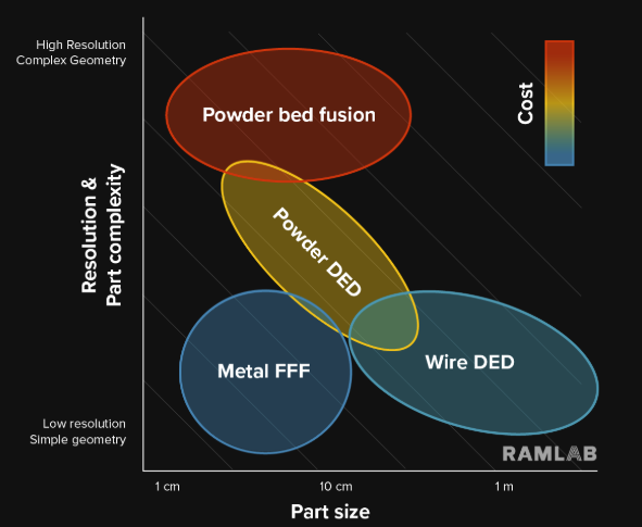
When designing a part for additive manufacturing, keep the intended production method in mind, as it defines the optimal geometry. Use the process selection overview and the per-process guidelines below to inform design decisions.
2.1 Material Extrusion (FDM / FFF)
The following guidelines concern plastic FDM printing. Metal material extrusion exists but is less common and not covered here.
2.1.1 Geometry and Feature Size
Table 1 – Geometry and feature size for FDM
| Aspect | Guideline | Why it matters |
|---|---|---|
| Minimum wall thickness | ≥ 2 × nozzle diameter (0.4 mm nozzle → ≥ 0.8 mm)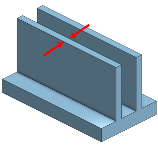 | Thin walls may not bond properly, leading to gaps or delamination. |
| Overhangs | ≤ 45° without support; steeper angles require support structures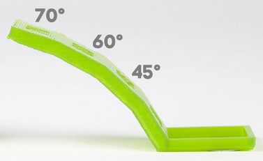 | Unsupported overhangs sag because the extruded filament has nothing to rest on. |
| Bridges | Keep spans ≤ 10 mm (material-dependent); use a low print speed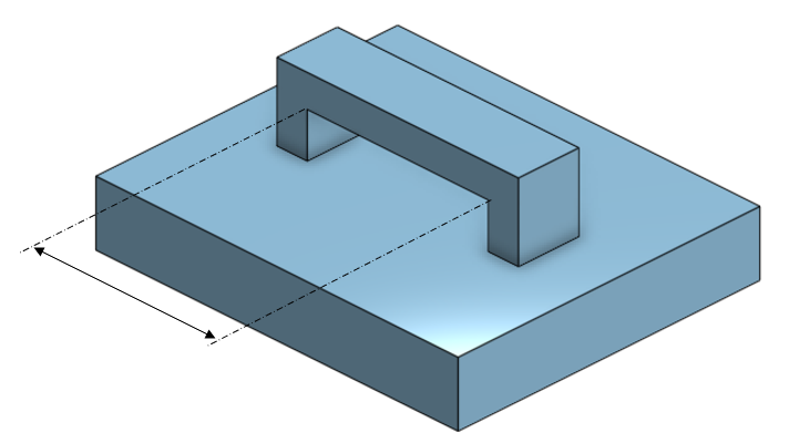 | Long bridges droop as the filament cools before it can solidify. |
| Small details | ≥ 0.5 × nozzle diameter for holes/slots; larger for raised features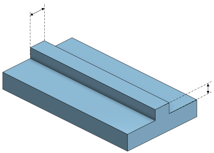 | Tiny features can be clogged or incompletely formed due to extrusion limits. |
| Fillet radius | ≥ 0.5 mm (or approximately 1 × nozzle diameter) | Sharp internal corners trap material and cause poor flow or weak points. |
| Orientation-dependent features | Align tall, slender elements vertically to reduce support volume | Reduces support material and improves surface quality on critical faces. |
| Maximum build envelope | Up to 900 × 600 × 900 mm on industrial FDM; desktop units typically ≤ 200 × 200 × 200 mm | Parts exceeding the envelope must be split and joined. |
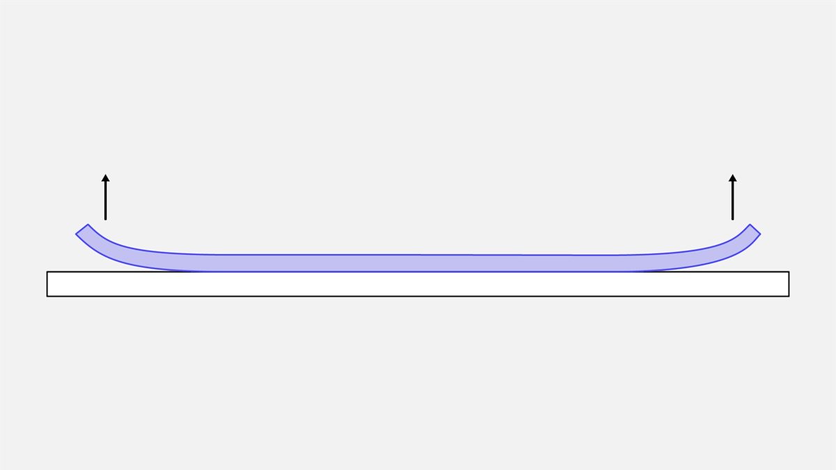
Warping is most common in ABS and Nylon. Use a heated enclosure, a brim or raft, and a higher ambient temperature to mitigate. Low-shrinkage materials (PLA, PETG) are less susceptible.
2.1.2 Part Orientation
Part orientation significantly affects strength, surface finish, and the amount of support material required. Key considerations:
- Strength direction: FDM parts are strongest along the raster (extrusion) direction and weakest across layer interfaces. Align the primary load path with the raster direction where possible.
- Support minimisation: Rotate the model to keep overhangs under 45°, limit contact points, and place the largest flat surfaces on the build plate.
- Surface finish: Faces that require a good visual finish should face upward or be placed against the build plate. Support-contact surfaces always have a rougher finish.
- Print speed: Orientation can influence print time but is usually a secondary concern.
2.1.3 Material Selection
Table 2 – Common FDM materials and their functional properties
| Material | Typical use cases | Key design impacts |
|---|---|---|
| PLA | Prototypes, decorative parts | Low warping – can print tall, thin features. Limited to ~60 °C continuous service. |
| PETG | Functional prototypes, containers | Good layer adhesion; moderate flexibility. Watch for stringing on tight corners. Up to ~88 °C. |
| ABS | Mechanical parts, automotive | Higher shrinkage – design larger tolerances, include draft angles, use a heated enclosure. Up to ~105 °C. |
| Nylon (PA) | Gears, wear parts | High impact resistance; requires generous clearances for moving parts. Moisture-sensitive – store filament dry. Up to ~50 °C. |
| Flexible (TPU / TPE) | Seals, grips | Requires slower print speeds and lower retraction; avoid features smaller than 1 mm. Up to ~100 °C depending on grade. |
| Carbon-fibre reinforced PLA / PETG | Stiff, lightweight components | More brittle – avoid sharp corners. Higher nozzle wear; use a hardened steel nozzle. |
This list is not exhaustive. Other commonly available filaments include Polycarbonate (PC), PolyEtherImide (PEI), ASA, and various composite grades. Consult supplier datasheets for specific mechanical and thermal properties.
2.1.4 Tolerances and Clearance
- Dimensional tolerance: ±0.2 mm for well-calibrated printers; ±0.5 mm for less precise machines.
- Moving parts clearance: Add at least 0.4–0.6 mm (≈ 1–1.5 × nozzle diameter) between mating surfaces.
- Threaded features: Print threads as a separate insert (metal or nylon) or design them approximately 10 % oversized and tap after printing.
2.1.5 Supports
- Support type: Use "tree" supports for delicate overhangs to reduce contact area and ease removal.
- Support density: 15–30 % infill for most plastics; increase to 40 % for ABS or Nylon to counteract warping.
- Interface layers: Add a few dense interface layers (≈ 0.2 mm) between the part and support to improve the surface finish where supports contact critical areas.
2.1.6 Print Settings That Influence Design
Table – Print settings and their effect on part design
| Setting | Effect on design | Recommended range |
|---|---|---|
| Layer height | Surface smoothness vs. detail resolution | 0.1 mm fine detail; 0.2 mm normal; 0.3 mm fast/coarse |
| Print speed | Dimensional accuracy, stringing | 40–60 mm/s (intricate, older printers); 100–200 mm/s (intricate, modern printers); up to 500 mm/s for simple shells |
| Infill pattern and density | Part stiffness and weight | 20–30 % honeycomb for balanced strength/weight; ~50 % grid or cubic for higher stiffness |
| Shell walls | Outer strength, sealing | ≥ 2 perimeters for most parts; ≥ 3 for load-bearing walls. More walls generally add more strength per unit material than more infill. |
| Cooling fan | Overhang quality, bridging | 100 % for PLA; 30–50 % for ABS/Nylon to reduce warping. Reduced cooling also reduces maximum bridge/overhang span. |
| Bed temperature | Adhesion, shrinkage control | 55–60 °C for PLA; 80–100 °C for ABS/Nylon; ~50 °C for PETG |
2.1.7 Post-Processing Considerations
- Sanding and smoothing: Design with extra material where sanding is planned (e.g., thicker walls).
- Acetone vapour smoothing (ABS only): Avoid tight tolerances in areas to be smoothed; the process removes approximately 0.1 mm from the surface.
- Annealing: Allow for dimensional change of up to 2 % after annealing; maintain sufficient clearance in mating features.
2.1.8 Common Pitfalls and Fixes
Table – FDM common pitfalls and corrective actions
| Pitfall | Symptom | Fix |
|---|---|---|
| Warping / lifting edges | Corners curl up; poor bed adhesion | Use a heated bed; apply brim/raft; increase ambient temperature; or switch to a low-shrink material (PLA, PETG). |
| Stringing on small features | Fine hairs between separated areas | Reduce retraction distance/speed; lower print temperature; enable "coasting". |
| Delamination | Parts split along layer lines under load | Increase extrusion temperature; reduce print speed; raise infill percentage; or redesign to align loads with the raster direction. |
| Clogged nozzle | Missing sections, under-extrusion | Clean the nozzle; use filtered filament; avoid abrasive composites without a hardened nozzle. |
| Poor dimensional accuracy | Holes too small/large; mismatched fits | Calibrate steps/mm; adjust flow multiplier; add clearance as noted above. |
2.2 Vat Photopolymerisation (SLA / DLP)
SLA and DLP share largely the same design rules. Minor differences arise from XY resolution – projector pixels (DLP) versus laser spot size (SLA) – and the fact that DLP quality decreases with tray density.
Table 3 – Geometry and feature size for SLA and DLP
| Aspect | Guideline | Why it matters |
|---|---|---|
| Minimum wall – supported | ≥ 0.4 mm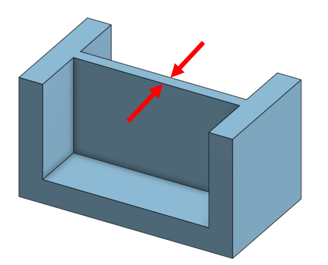 | Supported walls connected on at least two sides have a low warping risk and can be designed thinner. |
| Minimum wall – unsupported | ≥ 0.6 mm; add filleted bases to reduce stress concentrations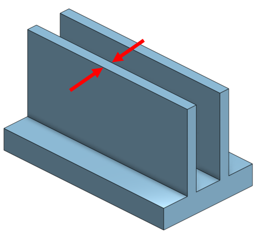 | Walls connected on fewer than two sides have a high risk of warping or detaching. |
| Overhangs | Without supports: ≤ 1 mm in length, ≥ 19° from horizontal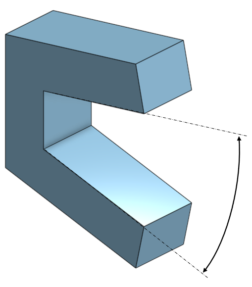 | Unsupported overhangs cause warping; with proper supports overhangs pose little issue. |
| Embossed details (including text) | ≥ 0.1 mm above surface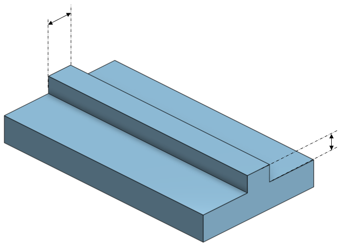 | Features below this threshold are not reliably visible after printing. |
| Engraved details (including text) | ≥ 0.4 mm wide and ≥ 0.4 mm deep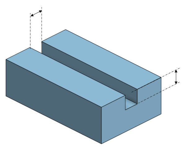 | Smaller features risk fusing closed during printing. |
| Horizontal bridges | Keep span < 21 mm (wider bridges must be shorter)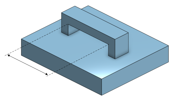 | Wider bridges have greater Z-axis contact area, increasing the risk of print failure during peeling. |
| Minimum hole diameter | ≥ 0.8 mm in all axes | Smaller holes may close off during printing. |
| Clearance – moving parts | 0.5 mm clearance on all sides | Ensures freedom of movement and support material removal. |
| Clearance – assembly connections | 0.2 mm clearance; 0.1 mm for push/snug fit | Provides consistent assembly fits. |
| Hollow section drain holes | ≥ Ø 3.5 mm; at least one hole per hollow section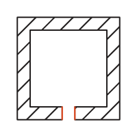 | Prevents uncured resin from becoming trapped inside, which causes pressure imbalance and part failure. |
| Hollow section wall thickness | ≥ 2 mm | Thinner hollow walls risk failure during printing. |
| Maximum build envelope | ~500 × 500 × 300 mm industrial; ~145 × 145 × 175 mm desktop SLA | Larger parts must be split into sub-assemblies. |
2.3 Powder Bed Fusion
To accommodate shrinkage, most PBF designs have overall dimensions scaled up by 3–3.5 % at the pre-print stage. This does not eliminate the need for post-print finishing of critical surfaces. To reduce warping of large flat surfaces, add ribs for stiffness and consider part orientation carefully during design.
2.3.1 Minimum Wall Thickness
Table – Minimum wall thickness by PBF process
| Process | Guideline | Reason |
|---|---|---|
| SLS | 0.8 mm (PA12) to 2 mm (carbon-filled polyamide) | Prevents excessive warping or weak features. |
| DMLS | 0.5 – 1 mm (AlSi10Mg, 316L, Ti-6Al-4V) | Metal powders fuse readily but thin unsupported walls still need support to avoid distortion. |
| SLM | 0.4 – 0.8 mm (Al, Ti, stainless steels) | Higher energy density gives stronger bonds, allowing thinner walls, but residual stress can cause warping. |
| EBM | 0.8 – 1.5 mm (Ti-6Al-4V, Co-Cr) | Larger melt pool and higher thermal gradients require slightly thicker walls for safety. |
| SHS | 0.8 – 1.5 mm | Binder-filled powder behaves more like a polymer matrix; metal particles do not fully melt. |
2.3.2 Embossed / Engraved Details
Table – Minimum embossed/engraved detail size
| Process | Minimum detail size |
|---|---|
| SLS / SHS | > 1 mm |
| DMLS / SLM | > 0.5 mm |
| EBM | > 0.8 mm |
Smaller features may be possible; discuss requirements with the supplier.
2.3.3 Text (Minimum Font Height)
Table – Minimum font height by PBF process
| Process | Minimum font height |
|---|---|
| SLS / EBM / SHS | 2 mm (font size 14); use sans-serif, ensure legibility in all orientations |
| DMLS | 1.5 mm |
| SLM | 1.5 mm (metal parts are often machined/polished after build; surface roughness ~30 µm Ra as-built limits effective minimum size) |
2.3.4 Tolerances
Table – Typical dimensional tolerances
| Process | Typical tolerance |
|---|---|
| SLS / SHS | ±0.3 mm (or ±0.3 %, whichever is larger) |
| DMLS | ±0.15 mm (≈ 0.1 % for high-precision systems) |
| SLM | ±0.12 mm (≈ 0.1–0.2 %) |
| EBM | ±0.2 mm (≈ 0.15 %) |
2.3.5 Feature Size (Pins, Protrusions)
Table – Minimum reliable feature size
| Process | Minimum feature size |
|---|---|
| SLS / SHS | > 0.8 mm (polymer-binder limited for SHS) |
| DMLS | > 0.8 mm (most alloys) |
| SLM | > 0.4 mm (high-resolution systems) |
| EBM | > 0.8 mm |
2.3.6 Distance Between Parallel Features
Table – Minimum gap between parallel features
| Process | Minimum gap |
|---|---|
| SLS / EBM / SHS | > 0.8 mm (to prevent bridging) |
| DMLS / SLM | > 0.6 mm (to prevent balling) |
For metal processes, features can be placed somewhat closer together, but ensure the gap is large enough for the powder recoater to fill the space completely. If the gap is too tight, voids or incomplete fusion may result.
2.3.7 Holes
Table – Minimum reliable hole size
| Process | Minimum hole size |
|---|---|
| SLS / SHS | ≥ 1.5 mm |
| DMLS | ≥ 1.0 mm |
| SLM | ≥ 0.8 mm |
| EBM | ≥ 1.2 mm |
For metal PBF processes, holes can be smaller before they close off compared to polymer processes, as metal powders sinter more completely. However, unsupported vertical holes can trap unmelted powder; adding a vent hole or planning a "drill-out" post-processing step is recommended.
2.3.8 Escape / Vent Holes (for Hollow Sections)
Table – Minimum vent hole size for hollow sections
| Process | Minimum vent hole size |
|---|---|
| SLS / SHS | ≥ Ø 3.5 mm; at least one hole per hollow section |
| DMLS / SLM | ≥ Ø 2 – 3 mm (2 mm is often sufficient) |
| EBM | ≥ Ø 3.0 mm |
For metal builds, powder removal is easier due to higher part density, so vent holes can be slightly smaller. However, thermal stresses in metal builds mean at least one vent per enclosed section is still required.
2.3.9 Maximum Build Envelope
Table – Maximum build envelope by PBF process
| Process | Typical build envelope |
|---|---|
| SLS | ~300 × 300 × 300 mm (desktop); up to 500 × 500 × 500 mm on industrial systems |
| DMLS | 250 × 250 × 300 mm typical; up to 400 × 400 × 400 mm on large systems |
| SLM | 250 × 250 × 280 mm standard; up to 500 × 500 × 500 mm on high-end systems |
| EBM | 300 × 300 × 300 mm to 500 × 500 × 600 mm depending on system |
| SHS | ~300 × 300 × 300 mm (similar to desktop SLS) |
If a part exceeds the build envelope, split it into sub-assemblies and join them afterwards (welding, brazing, or mechanical fasteners). The same principle applies when the build volume cannot accommodate the required quantity of parts.
2.3.10 Materials
Table 4 – Materials for PBF printing
| Material | Process | Characteristics |
|---|---|---|
| PA12 | SLS, SHS | Good dimensional stability, wear and chemical resistance; widely used for functional polymer PBF parts. |
| PA11 | SLS | Higher ductility and impact resistance than PA12; suited where toughness and elongation are important. |
| Glass- / mineral-filled polyamide | SLS | Higher stiffness and dimensional stability than unfilled nylon, but more brittle. |
| Carbon-filled polyamide | SLS | High stiffness, good strength-to-weight ratio, reduced deformation, lower ductility. |
| TPU | SLS | Flexible, elastomeric; suitable for seals and damping elements. |
| PP | SLS | Lower density, good chemical resistance, good fatigue behaviour. |
| PEEK / PEKK | High-temperature laser PBF systems | Very high temperature resistance and mechanical performance; specialist and less common. |
| 316L stainless steel | DMLS, SLM | Good corrosion resistance, good ductility, broad industrial applicability. |
| 17-4PH stainless steel | DMLS, SLM | Higher strength than 316L; suitable for heat treatment. |
| AlSi10Mg | DMLS, SLM | Lightweight, good strength-to-weight ratio, good thermal conductivity; widely used in lightweight structures. |
| Ti-6Al-4V | DMLS, SLM, EBM | High strength-to-weight ratio, corrosion resistance, biocompatibility; widely used in aerospace and medical. |
| Cobalt-chrome | DMLS, SLM, EBM | High wear resistance, corrosion resistance, biocompatibility. |
| Inconel 625 / 718 | DMLS, SLM, EBM | High-temperature strength and oxidation resistance; suitable for demanding thermal environments. |
| Maraging steel / tool steels | DMLS, SLM | High strength and hardness after heat treatment; suitable for tooling and structural parts. |
2.4 Jetting Processes
2.4.1 Material Jetting (PolyJet)
Material Jetting produces near-homogeneous parts and supports multi-material printing. Its principal limitation is brittle mechanical behaviour.
Table 5 – Geometry and feature size for Material Jetting
| Aspect | Guideline | Why it matters |
|---|---|---|
| Minimum wall – supported | > 1 mm | Minimum wall thickness for major supported walls. |
| Minimum wall – unsupported | > 0.5 mm | Minimum for all other walls. |
| Pin diameter | > Ø 0.5 mm | Minimum recommended pin diameter. |
| Details | As small as 0.25 mm is achievable | Material Jetting offers very high resolution for fine details. |
| Embossed / engraved details (including text) | ≥ 0.5 mm depth/height | Ensures small details are reliably visible. |
| Minimum hole diameter | > Ø 0.5 mm; orient holes vertically where possible | Vertical orientation maximises hole circularity. |
| Clearance – moving parts / hinges | 0.15 – 0.2 mm clearance on all sides | Allows support material removal from gaps. |
| Dimensional tolerance | ±0.1 mm to ±0.3 mm (geometry and material dependent) | Sets the baseline for fit design. |
| Maximum build envelope | ~290 × 200 × 140 mm (contact supplier) | Larger parts must be split. |
Table – Material Jetting materials overview
| Material category | Typical applications | Notes |
|---|---|---|
| Standard rigid opaque | High-detail, non-functional prototypes | Generally PE-like, brittle. Available in white, black, grey, blue. |
| Transparent | Clear prototypes and models | Can be post-processed to full optical transparency. |
| ABS-like | Parts simulating ABS properties | Higher temperature range and strength; minimum wall thickness 0.85 mm. More brittle than FDM or moulded ABS. |
| Polypropylene-like | Flex and snap features | Excellent for snap fits; more brittle than injection-moulded PP. |
| Flexible (rubber mimic) | Gaskets, seals, overmoulds, buttons | Custom durometer blends available; not suited for high elongation/stretch applications. |
| High temperature | Hot-air/water flow testing; up to ~90 °C | Requires thermal post-processing to reach maximum heat resistance. |
| Castable | Investment casting patterns (dental, jewellery) | Near 100 % burn-out; very high detail resolution. |
| Biocompatible | Dental and medical applications | Designed for sterilisation and short-term biocompatibility. |
2.4.2 Binder Jetting
After Binder Jetting, parts are in a fragile green state and require post-processing (infiltration or sintering) before use.
Table 6 – Geometry and feature size for Binder Jetting
| Aspect | Guideline | Why it matters |
|---|---|---|
| Minimum wall – supported | > 2 mm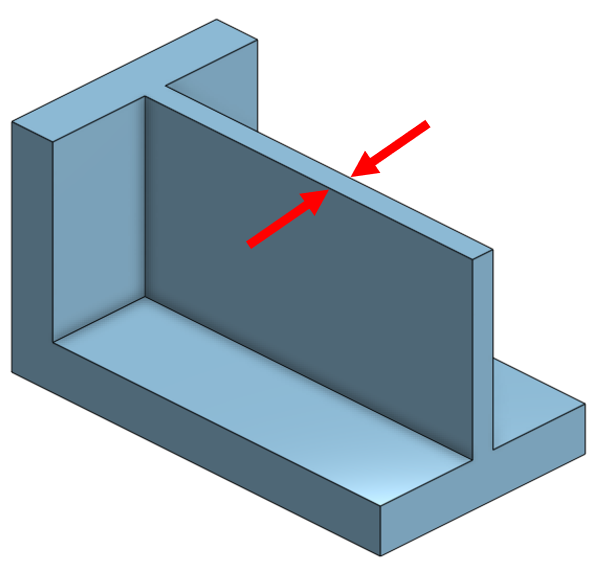 | Ensures the part can be handled in the green state without damage. |
| Minimum wall – unsupported | > 3 mm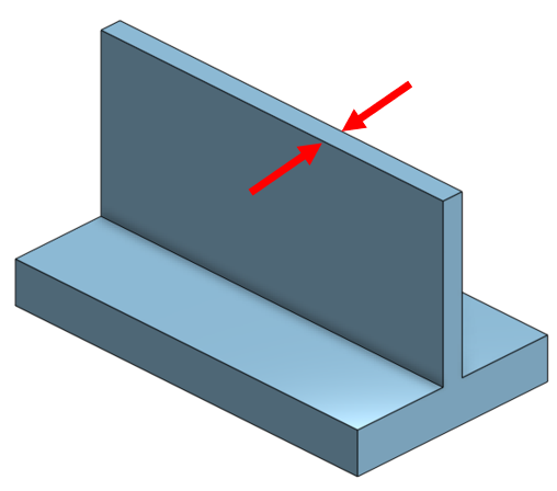 | Unsupported walls (fins, ribs) are at higher risk during green-state handling. |
| Unsupported edges | < 20 mm in length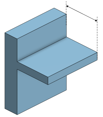 | Longer unsupported edges are prone to breaking during green-state handling. |
| Embossed / engraved details | ≥ 0.5 mm | Ensures details are visible after depowdering and post-processing. |
| Fillets | Radius > 1 mm on all edges where possible | Reduces risk of damage in the green state; aids powder removal from internal cavities. |
| Minimum hole diameter | > Ø 1.5 mm | Ensures holes print successfully and can be cleared of powder. |
2.4.3 Multi Jet Fusion (MJF)
MJF enables production of functional parts at reduced cost and lead time compared to SLS and injection moulding, especially for low to medium volumes.
Table 7 – Geometry and feature size for MJF
| Aspect | Guideline | Why it matters |
|---|---|---|
| Minimum wall thickness | ≥ 2.5 mm | Thin walls may warp, become fragile or break during depowdering and handling. |
| Maximum wall thickness | Avoid solid sections > 12 mm; use ribs or lattice structures instead | Very thick sections cool unevenly, causing internal stress, surface defects and warpage. |
| Minimum feature size | ≥ 0.5 – 0.8 mm for embossed/debossed details, text, ribs | Finer details may not resolve reliably due to powder grain size and thermal effects. |
| Minimum hole diameter | ≥ 1.5 – 2.0 mm for through-holes; ≥ 3.0 mm for long or deep holes | Ensures holes can be cleared of powder during depowdering. |
| Internal channels | Minimum channel Ø ≥ 3.0 – 3.5 mm; at least two escape holes per enclosed cavity | Ensures unfused powder can be fully removed. |
| Powder escape holes | ≥ Ø 3.5 mm; use multiple openings for large/complex cavities | Sufficient vent size is needed to clear powder without damaging the part. |
| Overhangs and bridges | Generally self-supporting; keep unsupported spans ≤ 20 – 30 mm where possible | Large flat spans can warp or sag as the part cools, especially in thin sections. |
| Minimum gap / clearance | ≥ 0.6 mm for post-assembly; ≥ 0.9 mm for moving mechanisms printed as one assembly | Prevents features from fusing together or trapping powder. |
| Text and markings | Stroke width ≥ 0.4 – 0.5 mm; height/depth ≥ 0.4 – 0.6 mm; use sans-serif fonts | Very fine text becomes unreadable after depowdering and post-processing. |
| Maximum build envelope | ~380 × 285 × 380 mm typical | Larger parts must be split and joined after printing. |
| Slender parts (aspect ratio) | Keep thickness ≥ 3 – 4 mm; add fillets and ribs | Slender parts are prone to warping or bending during build and cooling. |
| Dimensional tolerances | ±0.2 mm for features ≤ 100 mm; add ±0.2 % of nominal above 100 mm | Sets a realistic baseline for fits; tighter tolerances may require post-processing. |
| Watertightness | Walls ≥ 1.0 mm for water-resistance; ≥ 3 – 4 mm for pressure-bearing features; use PA 12 powder | Thicker walls and correct post-processing reduce porosity and improve leak tightness. |
2.5 Directed Energy Deposition
Because DED is often used for repair, the geometry and accessibility of the existing component strongly constrain what is achievable. When designing a new component intended for future DED repair, build in sufficient material volume and tool-access clearance around wear zones.
2.5.1 Laser Metal Deposition (LMD)
Table 8 – Geometry and feature size for LMD
| Aspect | Guideline | Why it matters |
|---|---|---|
| Typical bead width | 1 – 3 mm (single track) | Defines minimum feature size, wall thickness, and machining allowance. |
| Layer height | 0.3 – 1 mm per layer | Too small: slow build; too large: poor surface and layer bonding. |
| Minimum wall / rib thickness | ≥ 1.5 – 2 × bead width (typically ≥ 2 – 4 mm) | Very thin walls are unstable during deposition and prone to distortion or collapse. |
| Maximum wall thickness | Use multiple passes or add internal cavities above 10 mm | Thick sections cool unevenly, increasing residual stress and risk of cracking. |
| Minimum feature size | ≥ 2 – 3 mm for stand-alone features | Smaller features cannot be reliably controlled with the melt pool. |
| Machining allowance | 0.5 – 1.5 mm per side on critical surfaces | Compensates for distortion, bead waviness and achieves final tolerances. |
| Overhangs | Prefer build angles ≥ 45° relative to substrate; avoid flat overhangs without support | Large overhangs are difficult to support with the melt bead and can sag or distort. |
| Minimum internal radius | ≥ 2 mm at corners | Reduces stress concentrations and improves bead continuity. |
| Pocket access | Pocket width ≥ 2 × outer diameter of LMD head; depth-to-width ratio ≤ 1.0; ≥ 10 – 15 mm radial clearance around melt pool area | Inadequate access prevents proper deposition and shielding, leading to defects. |
| Dimensional tolerance (near-net) | Typically ±0.5 – 1 mm before machining | Reflects realistic accuracy of as-deposited geometry. |
2.5.2 Electron Beam Additive Manufacturing (EBAM)
Table 9 – Geometry and feature size for EBAM
| Aspect | Guideline | Why it matters |
|---|---|---|
| Typical bead width | 2 – 6 mm (or more, system-dependent) | Sets the minimum thickness of walls, ribs, and other features. |
| Layer height | 1 – 3 mm per layer | Larger layers enable high deposition rate but reduce geometric resolution. |
| Minimum wall / rib thickness | ≥ 1.5 – 2 × bead width (typically ≥ 4 – 8 mm) | Ensures stable builds at high deposition rates. |
| Maximum wall thickness | Hollow out and add ribs for sections > 15 – 20 mm | Very thick sections amplify thermal gradients and residual stress. |
| Minimum feature size | ≥ 4 – 6 mm for stand-alone features | Smaller features are difficult to control with large beads and high heat input. |
| Machining allowance | 1 – 3 mm per side on critical surfaces | Compensates for higher distortion and rougher as-built surface than LMD. |
| Overhangs | Build at ≥ 45° where possible; avoid long horizontal features without support | Large flat overhangs increase risk of deformation and lack of fusion. |
| Minimum internal radius | ≥ 3 mm in highly loaded areas | Reduces risk of crack initiation in high-strength alloys. |
| Chamber limits | Conform all parts to the vacuum chamber envelope; consider rotation/tilt options | Parts exceeding chamber limits or kinematics cannot be built in a single setup. |
| Dimensional tolerance (near-net) | Often ±1 – 2 mm before machining | Captures realistic capability of large-scale EBAM builds. |
2.6 Sheet Lamination
2.6.1 Laminated Object Manufacturing (LOM)
LOM is best suited to relatively large, simple geometries with moderate surface detail. Avoid features relying on high interlaminar strength. Thin freestanding elements and sharp re-entrant features are particularly difficult to produce reliably.
Typical design considerations for LOM:
- Prefer broad, well-supported geometries; avoid long, fragile cantilevers.
- Keep internal corners and transitions smooth where possible to reduce tearing and improve layer registration.
- Account for the sheet thickness in the Z-direction; stepped surfaces become more visible on shallow slopes and curved surfaces.
- Plan post-processing – sanding, sealing, or coating – when visual appearance is important.
Table 10 – Geometry and feature size for LOM
| Aspect | Guideline | Why it matters |
|---|---|---|
| Layer thickness | Determined by sheet material; account for visible stair-stepping on shallow slopes | Vertical resolution is limited directly by sheet thickness. |
| Minimum wall thickness | ≥ 1 – 2 mm for non-structural models; more for tall or fragile features | Thin walls are prone to tearing, delamination, and handling damage. |
| Minimum feature size | Avoid stand-alone features < 1 – 2 mm | Limited by sheet thickness, adhesive spread, and cutting accuracy. |
| Minimum hole / slot size | ≥ 1 – 2 mm depending on material and cutting method | Very small features may not be cut cleanly. |
| Internal cavities | Keep simple; ensure surrounding waste material can be removed | Closed cavities may trap waste material that cannot be cleared after the build. |
| Corner radii | Prefer internal radii ≥ 0.5 – 1 mm where possible | Sharp corners are more prone to tearing during cutting. |
| Application scope | Best for visual models, mock-ups, and concept verification | Mechanical performance is limited by the laminated bond and material system. |
2.6.2 Ultrasonic Additive Manufacturing (UAM)
UAM (also called ultrasonic consolidation) bonds metal foils or ribbons in the solid state using ultrasonic vibration and pressure, with intermediate CNC machining to define the final geometry. It is particularly attractive for multi-material metallic structures, embedded sensors or wires, and parts with internal channels that would be difficult to produce by conventional machining alone.
Table 11 – Geometry and feature size for UAM
| Aspect | Guideline | Why it matters |
|---|---|---|
| Foil thickness | Typically 0.1 – 0.15 mm per layer; account for this directly in Z-resolution | Vertical resolution and minimum step height are set by foil thickness. |
| Bonded contact area | Ensure sufficient planar overlap; avoid very small isolated bonding islands | Reliable ultrasonic bonding requires adequate contact area and pressure transfer. |
| Minimum wall thickness | ≥ 1 – 2 mm depending on material and machining strategy | Very thin walls may distort during intermediate machining or bond inconsistently. |
| Minimum feature size | Avoid isolated metallic features < 1 mm unless validated with the supplier | Final resolution depends on both foil bonding and CNC finishing capability. |
| Internal channels | Size conservatively: ≥ 1 – 2 mm; ensure machining access during creation | UAM is strong for embedded channels, but subtractive steps still limit achievable geometry. |
| Embedded components | Reserve at least several foil layers of cover thickness above embedded sensors, wires, or inserts | Prevents exposure or damage during subsequent machining and bonding steps. |
References
| Reference | Purpose |
|---|---|
| ISO/ASTM 52920 | General principles and qualification standard for industrial additive manufacturing. |
| Additive Manufacturing Technologies, 2nd ed. – Gibson, Rosen, Stucker (2015) | Background information on additive manufacturing techniques. |
| Hubs 3D printing design guide (hubs.com) | Practical design guidelines for various AM processes. |